
forces acting on the aircraft during a glide
our thanks
www.raa.asn.au
(Copyright John Brandon)
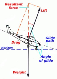
In a gliding descent
the forces are as shown in the diagram on the
left. In the case of a constant rate descent the
weight is exactly balanced by the resultant force
of lift and drag. From the dashed parallelogram of
forces shown it can be seen that the tangent of
the angle of glide equals drag/lift.
For example assuming a glide angle of 10°, from
the abridged trigonometrical table the tangent of
10° is 0.176, so the ratio of drag/lift in this
case is then 1 : 5.7. (A little more accurate
than using the '1-in-60' rule but inconsequential
anyway.)
Conversely we can say that the angle of glide is
dependent on the ratio of lift/drag at the
airspeed being flown and the lower that ratio is
then the greater the glide angle and consequently
the greater the rate of sink and the lesser the
distance the aircraft will glide from a given
height. The rate of sink is the resultant of the
gliding angle and the airspeed.
Be aware that the aircraft manufacturer's quoted
L/Dmax may be overstated and will not
take into account the considerable drag generated
by a windmilling propeller [see below] so, for
glide ratio purposes, it might be advisable to
discount the quoted L/Dmax by maybe
20%. But the best option is to check it yourself.
Abridged
trigonometrical table
Relationship between an angle within a
right angle triangle and the sides:
Tangent of angle=opposite side/adjacent
Sine of angle=opposite/hypotenuse
Cosine of angle=adjacent/hypotenuse
|
| Degrees |
Sine |
Cosine |
Tangent |
|
Degrees |
Sine |
Cosine |
Tangent |
| 1 |
0.017 |
0.999 |
0.017 |
|
50 |
0.766 |
0.643 |
1.192 |
| 5 |
0.087 |
0.996 |
0.087 |
|
55 |
0.819 |
0.574 |
1.428 |
| 10 |
0.173 |
0.985 |
0.176 |
|
60 |
0.866 |
0.500 |
1.732 |
| 15 |
0.259 |
0.966 |
0.268 |
|
65 |
0.910 |
0.423 |
2.145 |
| 20 |
0.342 |
0.939 |
0.364 |
|
70 |
0.939 |
0.342 |
2.747 |
| 30 |
0.500 |
0.866 |
0.577 |
|
75 |
0.966 |
0.259 |
3.732 |
| 40 |
0.643 |
0.766 |
0.839 |
|
80 |
0.985 |
0.173 |
5.672 |
| 45 |
0.707 |
0.707 |
1.000 |
|
90 |
1.000 |
0 |
infinity |
|
The aoa associated
with maximum L/D decides the best engine-off glide
speed (Vbg) according to the operating weight of
the aircraft. There are two glide speeds that the
pilot must know and – more importantly – be
familiar with the aircraft attitude
associated with those airspeeds so that when the
engine fails you can immediately assume [and
continue to hold] the glide attitude without more
than occasional reference to the ASI:
• Vmd – the minimum descent – the
speed that results in the lowest rate of sink in a
power-off glide, providing the longest time in the
air from the potential energy of height. The
lowest rate of sink occurs at the minimum value of
drag × velocity and, as stated above, may be
around 90% of Vbg. Vmd is the airspeed used by
gliders when utilising the atmospheric uplift from
thermals or waves. This is the airspeed to select
should you be very close to a favourable landing
site with ample height and a few more seconds in
the air to sort things out would be welcome.
Vmd decreases as the aircraft weight decreases
from MTOW and the percentage reduction in Vmd is
half the percentage reduction in weight. i.e. If
weight is 10% below MTOW then Vmd is reduced by
5%. Vbg is also reduced in the same way if weight
is less than MTOW.
• Vbg – the best power-off glide –
the CAS that provides minimum drag thus maximum
L/D, or glide ratio, consequently greatest
straight line flight [i.e. air] distance available
from the potential energy of height. The ratio of
airspeed to rate of sink is about the same as the
L/D ratio, so if Vbg is 50 knots [5 000 feet per
minute] and L/Dmax is 7 then the rate
of sink is about 700 fpm.
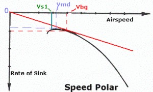
This 'speed polar' diagram is
a representative plot of the relationship between
rate of sink and airspeed when gliding. Vmd is at
the highest point of the curve. Vbg is ascertained
by drawing the red line from the zero coordinate
intersection tangential to the curve, Vbg is
directly above the point of contact. Stall point
is shown at Vs1.
Much is said about
the importance of maintaining the 'best gliding
speed' but what is important is to maintain an
optimum glide speed; a penetration
speed which takes atmospheric conditions into
account, for example sinking air or a headwind.
The gliding community refers to this as the
speed to fly. The normal recommendation for
countering a headwind is to add half the estimated
wind speed to Vbg which increases the rate of sink
but also increases the ground speed. For a
tailwind deduct half the estimated wind speed from
Vbg which will reduce both the rate of sink and
the groundspeed. Bear in mind that it is better to
err towards higher rather than lower airspeeds.
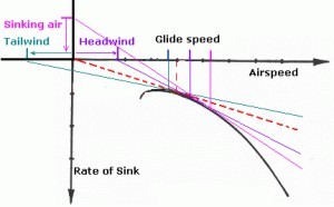
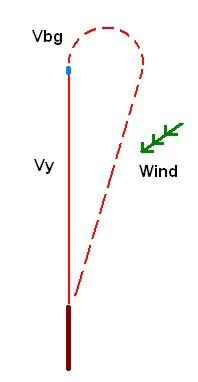
To illustrate this
the polar curve on the left indicates the optimum
glide speed when adjusted for headwind, tailwind
or sinking air. For a tailwind the starting point
on the horizontal scale has been moved a distance
to the left corresponding to the tailwind
velocity, consequently the green tangential line
contacts the curve at an optimal glide speed which
is lower than Vbg with a slightly lower rate of
sink. The opposite for a headwind – purple line.
For sinking air the starting point on the vertical
scale has been moved up a distance corresponding
to the vertical velocity of the air and
consequently the pink tangential line contacts the
curve at a glide speed higher than Vbg.
effect of a
windmilling propeller
Both
Vbg distance and Vmd time are adversely affected by
the extra drag of a windmilling propeller,
which creates much more drag than a stopped
propeller following engine shut-down. If the forward
speed is increased windmilling will increase, if
forward speed is decreased windmilling will
decrease, thus the windmilling may be stopped by
temporarily reducing airspeed so that the negative
lift is decreased to the point where internal engine
friction will stop rotation.
However do not attempt to halt a windmilling
propeller unless you have ample height and stopping
it will make a significant difference to the
distance covered in the glide. Sometimes it may not
be possible to stop the windmilling.
practical glide
ratio and terrain footprint
You
should measure [preferably by stop watch and
altimeter] the actual rate of sink achieved at Vbg
with the throttle closed [engine idling], and from
that you can calculate the practical glide ratio
for your aircraft. The practical glide ratio is Vbg
[in knots multiplied by 100 to convert to feet per
minute] divided by the rate of sink [measured in
fpm]. For example glide ratio when Vbg 60 knots,
actual rate of sink 750 fpm = 60 × 100/750 = 8, thus
in still air that aircraft might glide for a
straight line distance of 8000 feet for each 1000
feet of height.
These measurements should be taken at MTOW and then,
if a two-seater, at the one person-on-board [POB]
weight with the reduced Vbg.
The airspeed used should really be the TAS but,
if the ASI is known to be reasonably accurate, using
IAS will err on the side of caution, also with
the engine idling a fixed pitch propeller will
probably be producing drag rather than thrust so
that too will be closer to the effect of a
windmilling propeller. You should also confirm the
rate[s] of sink at Vmd.
Having established the rates of sink you then know
the maximum airborne time available. For example if
the rate of sink at Vbg with one POB is 500 fpm and
the engine fails at 1500 feet agl then the absolute
maximum airborne time available is three minutes. If
failure occurs at 250 feet whilst climbing then time
to impact is 30 seconds, but 3 or 4 seconds might
elapse before reaction occurs plus 4 or 5 seconds
might be needed to establish at the safe glide
speed. Read the section on conserving energy in the
Flight Theory Guide.
Following engine failure it is important to be able
to judge the available radius of action i.e. the
maximum glide distance in any direction. This
distance is dependent on the following factors, each
of which involves a considerable degree of
uncertainty:
 the practical glide ratio
the topography [e.g. limited directional choice
within a valley]
the height above suitable landing areas
turbulence, eddies and downflow conditions
manoeuvring requirements
and the average wind velocity between current
height and the ground.
The
footprint is shifted downwind i.e. the into-wind
radius of action will be reduced while the downwind
radius will be increased. The wind velocity is going
to have a greater effect on an aircraft whose Vbg is
45 knots than on another whose Vbg is 65 knots.
Atmospheric turbulence, eddies and downflows will
all contribute to loss of height. Rising air might
reduce the rate of descent.
Considering the uncertainties involved [not least
being the pilot's ability to judge distance] and
particularly should the engine fail at lower heights
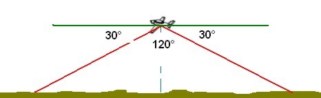
where time is in short supply, it may be valid to
just consider the radius of the footprint as twice
the current height – which would encompass all the
terrain within a 120° cone and include some
allowance for manoeuvring. The cone encompasses all
the area contained within a sight line 30° below the
horizon. If you extend your arm and fully spread
the fingers and thumb the angular distance between
the tips of thumb and little finger is about 20°.
There is a drawback in that total area available
from which to select a landing site is considerably
reduced; the area encompassed within a radius of 60%
of the theoretical glide distance is only about one
third of the total area.
For powered chutes the radius of the footprint might
be equivalent to the current height providing a 90°
cone from a sight line 45° below the horizon.
Know the height lost during manoeuvres
Any
manoeuvring involved in changing direction/s will
occasion an increased loss of height and thus reduce
the footprint. This reduction will be insignificant
when high but may be highly significant when low.
The increase in height loss during a gliding turn
is, of course, dependent on the angle of bank used
and the duration of the turn. Properly executed,
gently banked turns which only change the heading
15° or so produce slight additional height loss [in
fpm terms] and a slight reduction in the margin
between Vbg and stalling speed, steeply banked turns
through 210° will produce significant additional
height loss and a major reduction in the margin
between Vbg and stalling speed. You should be very
aware of the height loss in 30°, 45° and 60° changes
of heading because they are representative of the
most likely turns executed at low levels.
Just because an aircraft has a good glide ratio does
not mean it will perform equally well in a turn, it
may lose more height in a turn than an aircraft
which has a poorer glide ratio. For example a nice
slippery aircraft with a glide ratio of 15 may lose
1000 feet in a 210° turn, whereas a draggy aircraft
with a glide ratio of only 8 might lose only 600
feet in a 210° turn. Of course the radius of turn is
greater in the faster, slippery aircraft.
Steepening the final
descent path
If
it is necessary to steepen the descent path to make
it into a clearing the use of full flaps and/or a
full
sideslip, a sideslipping turn from base or careful
fishtailing is usually recommended. A series of 'S'
turns will reduce the forward travel. These
techniques are certainly not something tried out for
the first time in an actual emergency, they should
only be used after adequate instruction and adequate
competency has been reached – and maintained. The
use of full flaps plus full sideslip may be frowned
upon by the aircraft manufacturer but in an
emergency situation use everything available.
height loss in a turn-back
When
the engine fails soon after take-off the
conventional and long proven wisdom is to, more or
less, land straight ahead, provided that course of
action is not going to affect others on the ground –
for example put you into a group of buildings. If
the engine fails well into the climb-out one of the
possible options is to turn back and land on the
departure field. If the take-off and climb was
into-wind and a height of perhaps 1500 feet agl had
been attained [and the rate of sink is significantly
less than the rate of climb] then there would be
every reason to turn back and land on that perfectly
good airfield. There might be sufficient height in
hand to manoeuvre for a crosswind rather than
downwind landing.
On the other hand there will be a minimum safe
height below which a 'turn-back' for a landing in
any direction could clearly not be accomplished. To
judge whether a safe turn-back is feasible the pilot
must know the air radius of turn and how much height
will be lost during the turn-back in that particular
aircraft in similar conditions, then double it
for the minimum safe height. Such knowledge can
only be gained by practising turn-backs at a safe
height and measuring the height loss.
Radius of turn and height loss
In a
turn-back to land on the departure runway it is
important to minimise both the distance the aircraft
moves away from the extended line of the runway and
the time spent in the turn. The slowest possible
speed and the steepest possible bank angle will
provide both the smallest radius and the fastest
rate of turn, however these advantages will be more
than offset by the following:
When the steepest bank angle and slowest speed is
applied the necessary centripetal force for the
turn is provided by the extra lift gained by
increasing the angle of attack ( or CL)
to a very high value. Also due to the lower
velocity a larger portion of the total lift is
provided by CL rather than V².
Consequently the induced drag will increase
substantially.
When turning it is not L/D that determines glide
performance but rather the ratio to the drag of
the vertical component of lift [Lvc]
which offsets the normal 1g weight, or Lvc
/D, and thus, due to the increase in induced drag,
Lvc /D will be less than normal L/D
resulting in an increase in the rate of sink and a
steeper glide path. Lvc /D degrades as
bank angle in the turn increases.
The stall speed increases with bank angle, or more
correctly with wing loading, thus the lowest
possible flight speed increases as bank in a
gliding turn increases.
Any mishandling or turbulence during turns at high
bank angles, near the accelerated stall speed, may
result in a violent wing and nose drop with
substantial loss of height.
Choosing the bank angle
In
some faster aircraft it might be found that the turn
back requires a steep turn, entered at a safe
airspeed [ say 1.2 × Vsturn ], where the
wings are slightly unloaded by allowing the nose to
lower a little further throughout the turn then,
having levelled the wings, converting any airspeed
gained into altitude by holding back pressure until
the airspeed again drops to the target glide speed,
not forgetting to allow for the ASI instrument lag.
The bank angle usually recommended is 45° because at
that angle the lift force generated by the wing is
equally distributed between weight and centripetal
force although the Vsturn will be
increased to about 1.2 × Vs1. Thus the safe airspeed
would be 1.2 × 1.2 × Vs1 = 1.44 Vs1. [1.5 Vs1 is
usually accepted as a "safe speed near the ground"
for gentle manoeuvres]. If the aircraft has a
high wing loading the sink rate in a steep turn may
be excessive. Refer turn forces and bank angle.
For aircraft at the lower end of the performance
spectrum it may be found that a 20° to 25° bank
angle provides a good compromise with an appreciable
direction change and a reasonable sink rate. There
may be other techniques for an aircraft fitted with
high lift devices. All of which indicates that
performance will vary widely and you must know your
aircraft and establish its safe turn-back
performance under varying conditions otherwise
never turn back!
Canadian statistics indicate
"if an engine failure
after takeoff results in an accident, the pilot is
at least eight times more likely to be killed or
seriously injured turning back than landing straight
ahead."
|
