The prime aim
in the landing sequence is to perform the operation safely, the secondary aim is
to touch down – usually – with minimum vertical speed and minimum horizontal
ground speed, consistent with maintenance of controllability – particularly in
gusty wind conditions. The touchdown should be made without excessive side
forces affecting the undercarriage. A not so important objective, is to touch
down close to a pre-selected position. The student pilot usually finds, of all
normal flight procedures, the techniques for landing an aircraft in varying
conditions, are the most difficult to master, because of the greatly enhanced
effects of air movement when close to the surface and the fine judgements and
control movements involved.
We will look at the common
factors to be considered in landing a normally configured, 3-axis, fixed
undercarriage, nosewheel or tailwheel aeroplane which may, or may not, be flap
equipped. Aircraft designed with full 'short take-off and landing' – STOL –
capability will use slightly different techniques in some parts of the approach
and landing. There are differing landing procedures or techniques, or
combinations thereof, applicable to airfield dimensions and surface conditions:
 normal landing
short field landing
soft field landing.
The basic landing sequence
is varied, according to prevailing conditions (and there is a varying degree of
alignment correction to allow for the crosswind component of the wind velocity),
but it usually has four parts:
-
Joining the circuit pattern
of the airfield, during which the aircraft is decelerated from cruise speed to
circuit speed, the airfield is visually checked for serviceability and
obstructions, surface wind direction ascertained from observation of the
windsock/s, the whereabouts of other traffic is established, the landing
direction and approach is planned and the pre-landing cockpit checks are
carried out in a logical sequence.
-
The approach
to the landing, during which the aircraft is decelerated from circuit speed to
the reference indicated approach speed [Vref ], configured for landing,
established in a constant rate of descent and aligned so that the flight path
traced over the ground during the final approach is on the same line as the
intended ground roll-out path. The flight path passes over an imaginary 50
feet high screen, placed at a distance before the airstrip threshold.
-
A transition
period where both the rate of descent and the forward speed are slowed during
a 'round-out' prior to touchdown.
-
The touchdown
and subsequent ground roll after which the aircraft is turned off the landing
area at an appropriate taxiing speed. The landing is then complete when the
aircraft is securely parked, the engine is off and any passenger is safely
disembarked.
The most favourable
conditions for optimum landing
performance at maximum weight are:
a pilot who exercises sound
judgement, follows the rules and the recommended procedures
a surface, of ample length,
that is dry and level, or with a slight upslope
a low density altitude i.e.
low elevation and low temperature
a smooth, full headwind of
reasonable and constant velocity.
Apart from the pilot's
condition and capability, landing performance is limited by the following
constraints, all of which should be carefully assessed – both within the
pre-landing procedure and at the flight planning stage – to establish whether
a safe landing is viable. Generally most of the engine effects and other
phenomena affecting take-off performance, have no significant effect on
landing performance except with both tailwheel and nosewheel aircraft, the
inertial effect of the cg position. However when a landing attempt is aborted
then any of those phenomena may be present during the initial go-around.
-
Demonstrated landing
distance. Landing distance is the
total distance required to clear an imaginary screen, 50 feet or 15 metres
high, placed before the airstrip threshold; then touch down and bring the
aircraft to a halt with normal braking – in nil wind conditions. It should be
borne in mind that the manufacturer's 'demonstrated' landing distance has been
achieved by a very experienced test pilot in very favourable conditions,
during the type certification tests. The landing distance required by the
average recreational pilot may be considerably greater.
-
Airfield dimensions and
slope. The usable length of runways or
strips must be ascertained, as well as the degree of slope – both with and
across the direction of landing. Landing downslope will reduce deceleration
and lengthen the ground roll. Slope across the landing path makes the
touchdown and subsequent ground roll more difficult to control. At a 'one-way'
airstrip a combination of airfield slope and rising terrain at the high end
mandates landing upslope, no matter what the wind direction.
-
Airfield surface and
surrounds. A short dry grass or rough
gravel surface might decrease the ground roll by 10% compared to that for a
smooth sealed surface. Wet or long grass might decrease the ground roll by
30%, however there is a possibility that a wet surface can induce aquaplaning,
adversely affect braking and/or result in a groundloop. Long grass can catch a
wingtip resulting in a groundloop. A soft or waterlogged surface might greatly
decrease the roll but increase the possibility of the aircraft tipping over
during the roll, or might prevent take-off if such is attempted during the
landing roll. The location and height of man-made obstructions, trees and
local topography must be assessed.
-
Airfield density altitude.
A critical factor which is often not correctly assessed; the density altitude
has a major effect on the approach speed (i.e. the true airspeed is
significantly greater than the indicated airspeed) and thus the ground speed
at which the aircraft touches down and the length of the subsequent ground
roll. Density altitude also affects the aircraft's climb-out performance
should the landing be aborted.
-
Wind velocity and
turbulence. Wind strength, direction,
downflow, gust intensity, surface turbulence and the potential for wind shear
events are normally the major considerations in landing performance, for a
properly maintained aircraft.
The pilot-in-command of an
aircraft must assess all the foregoing factors and conditions to ascertain the
total distance required for obstacle clearance and landing; judge if the landing
can be safely conducted; and ascertain a safe escape route if the landing should
need to be aborted. All the foregoing assumes that the height of the cloud
base allows sufficient visibility and appropriate terrain and obstruction
clearance within the circuit. The problem for the less cautious pilot, if the
airfield conditions are found to be unsuitable, is that an eventual landing is
mandatory and, if flight planning was poor, there may be no acceptable
alternative airfield within range.
the overhead join
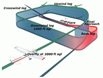
A standard procedure has been
adopted for any piston-engine light aeroplane approaching to land at an
airfield. This procedure is called the standard circuit pattern and is adopted
by convention rather than laid down by regulation. In regulated airfields, the
pilot should follow the instructions of the air traffic controller who will
probably request that you make a call some distance from the airfield. The
circuit requires that an aircraft should track over at least three legs of a
rectangular course aligned with the runway or landing strip which is most
into-wind. Turns, once established within the circuit, will all be in the same
direction, usually to the left unless otherwise stated; and the downwind leg
will be flown at moderate speed, adjusted to avoid overtaking preceding
aircraft, and holding a constant height – normally 1000 feet above the airfield
level. If the traffic circuit is left hand, approach the airfield keeping it to
your left. You should approach the airfield keeping it to your right if the
circuit is right hand.
The pilot must then manoeuvre so
that he/she crosses the threshold of the landing runway before descending from
2000 feet on the 'dead' side of the active runway, tracking close and parallel
to that runway. This is the upwind or into-wind leg. This gives
the opportunity to carefully check the airfield area and boundaries for hazards
– animals, power lines and other wires, ditches, obstructions and to ascertain
the whereabouts of other traffic in, or joining, the circuit and to be seen by
them. All manoeuvring should be done so that the airfield activities always
remain in sight, i.e. don't turn away for a short time and then follow with a
reversed turn onto downwind. Care should be taken when joining overhead as other
aircraft can also be joining.
When circuit height is reached and the upwind end of the runway has been passed,
choose an appropriate position to turn onto the crosswind leg so that
there will be no conflict with traffic on the crosswind and downwind legs, and
optimum traffic spacing will be achieved. You are now entering the traffic side
of the circuit: watch for aircraft joining the circuit on crosswind and for
aircraft taking-off; ensure that you provide adequate clearance. Maintain
circuit height and, allowing for drift, track at 90° to the runway.
Turn 90° onto the downwind leg at an appropriate distance past the runway
(after checking for aircraft joining the circuit on the downwind leg) check the
crosswind drift against selected landmarks and adjust heading to track parallel
to the runway, perform the appropriate downwind cockpit checks and make a
downwind call to ATC and hold altitude and appropriate traffic spacing. Set
power and trim the aircraft to maintain an airspeed which allows time to plan
the landing without unnecessarily delaying other traffic – probably around 1.7 ×
Vso.
Note that although we call these
legs 'upwind', 'crosswind' and 'downwind' they are only
nominally so as the surface wind is unlikely to be exactly aligned with the
'into-wind' runway or a single airstrip, and the wind at circuit height might
vary considerably from that at the surface.
Planning time! Select an intended touchdown target on the airstrip. This
should be far enough into the strip that an undershoot on approach will still
allow normal roundout and touchdown on the runway, or an overshoot on approach
will still allow ample runway to bring the aircraft to a halt. For most light
aircraft the latter requirement is probably inconsequential for most runways at
public aerodromes. The figures will vary according to the aircraft's drag
characteristics in the landing configuration.
At an appropriate distance past the aiming point turn 90° onto the base leg,
hold airspeed but reduce power so that a descent is started during the turn.
Lower the first stage flap if so equipped. Reduce airspeed [but not less than
1.5 × Vso] and trim.
The time spent flying base leg is most important, providing the opportunity to
set up the aircraft in the approach attitude; to establish a power and flap
setting [and trim] for the required rate of descent; to check for conflicting
traffic both airborne and on the ground and particularly any traffic on a
straight-in approach or very wide circuit; to assess the crosswind component
along the landing path; to decide the touchdown technique appropriate for the
conditions and to review the pre-landing checks.
Hold an accurate heading on base to carefully monitor drift, comparing the wind
velocity at that height with the surface wind indicated by the windsock. A
significant difference between the two indicates wind shear will be encountered
during the final approach; which may erode the safety margin between the
approach speed and Vso, or cause other difficulties. Never be tempted to fly a
semi-circular base with a short final approach – it is very poor airmanship
negating all the check features of the square base leg.
It may be that preceding traffic conditions preclude a turn onto base at the
optimum position, in which case speed must be reduced and/or the downwind leg
must be extended further downwind, altitude maintained and the start of descent,
and some actions, delayed until the aircraft is well into the base leg or even
established on final approach.
Start a 90° descending turn onto the final approach so that, on
completion of the turn, the aircraft is lined up with the extended notional
centre(line) of the landing strip. During the turn be aware of the reversal
height phenomena and confine external scanning to the intended flight path and
to the check for conflicting aerial traffic. If satisfied with the initial
approach lower full flap – if the wind speed is fairly high partial flap may
suffice – adjust airspeed to the recommended final approach speed [Vref] and
re-trim. On controlled airfields, an RT call of 'final' is given, and permission
to land is then granted by ATC.
In the final approach, once flaps are set, the airspeed and the rate of descent
are controlled with both elevator and throttle. The power setting should be such
that it allows small power reductions, or power increases, in order to maintain
the approach path; this can't be done if the approach is set up with the engine
at idle power. In addition the thrust response is not that effective from an
idle setting and, for many aircraft, an approach at idle power will entail a
high sink rate which may be difficult to manage. Also an idle power approach
tends to over-cool the engine and may promote carburettor icing both of which
may result in high power not being available when needed – such as in a
go-around.
Continue tracking down 'final', whilst correcting for the crosswind component,
and watching the position and apparent movement* of the aiming point relative to
the windscreen; then at 50 feet or so substantially reduce the rate of descent,
reduce thrust to zero, touchdown and roll-out until safe to turn off the landing
strip.
If so equipped, and in a nosewheel aircraft, brakes may be applied to slow the
aircraft during the latter part of the roll-out but only if the aircraft is
moving in a straight line on a firm surface and the elevators are raised to keep
excess weight off the nose wheel. In a tailwheel aircraft be very wary of any
brake application during the roll-out.
Variations on joining the circuit
The foregoing is the full
circuit pattern which should be adopted when inbound to an unfamiliar airfield.
However when inbound to an airfield which is well known to you, and you are
aware of the current runway in use and its serviceability, it may not be
necessary to overfly the airfield and the circuit may be joined anywhere on the
green path i.e. on the upwind, crosswind or downwind leg. Downwind joins are
normally made at a 45 degree angle from outside the pattern. When joining
crosswind or downwind you should already be at the circuit height.
Note that only the pattern of the standard circuit is fixed, its dimensions,
e.g. the length of the downwind leg or its distance from the runway, are
variable; but it is good practice to fly a nice, tight circuit. This also allows
a forced landing to be safely accomplished on the airfield should power be lost.
