automatic
direction finder
(ADF)
Some aircraft are equipped with
an ADF receiver. They receive radio signals in the medium frequency band of 190
Khz to 1750 Khz. The ADF receiver can “Home” on both AM radio stations and
Non-Directional Beacons. Commercial AM radio stations broadcast on 540 to 1620
Khz. Non-Directional Beacons (NDBs) operate in the frequency band of 190 to 535
Khz.
The aircraft equipment consists
of two antennas, the ADF Receiver, and the ADF Instrument. The two antennas are
called the (1) LOOP antenna and the (2) SENSE antenna.
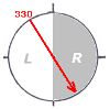
The loop antenna can sense the
direction of the signal from the station, but cannot discriminate whether the
station is in front or behind the aircraft. The sense antenna can discriminate
direction, and solves the ambiguity of the loop antenna.
The receiver unit has tuning
dials to select the station frequency A volume control allows the audible volume
to be controlled for identifying the station. The volume can be reduced to
prevent interference with other communications. You should, however,
continuously monitor the identifier while using the NDB for navigation.
|
The navigational display contains a compass
rose dial graduated in 5 degree increments from 0° to 355°, a pointer with
an arrow on one end, and a square form on the other end. We will call the
arrow end the “Pointer”, and the square end the “Tail” for the sake of
identification. |
There are 2 types of compass
rose dials that can exist in the navigational unit. One is a fixed compass rose,
called a “Fixed Card” ADF. Zero degrees is always shown on top of the card. The
“Rotateable Card” ADF allows the compass rose card to be rotated. Interpretation
of these displays will be more fully described in later paragraphs.
Non-Directional Beacon (NDB)
 |
Non-Directional Beacons are
depicted on aeronautical charts as a circular band of magenta coloured dots.
A rectangular magenta box near the NDB symbol shows the name of the station,
the 2 or 3 letter identifier, and the Morse code transmitted by the station.
|
NDBs may be located on the
surface of airports, or may be within a few miles from an airport. Sometimes
they are co-located with the Outer Marker in ILS approaches. The NDB provides
two principal functions; (1) homing for VFR operations, and (2) ADF instrument
approach capability for IFR operations.
Because the frequency is below
and within the commercial AM band, reception is subject to the same atmospheric
disturbances as AM radio, in particular, noise generated by lightening.
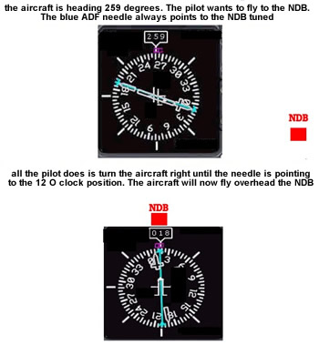
ADF Orientation
The pointer end of the ADF
navigation unit ALWAYS POINTS TO THE STATION. The degree reading on the display
is dependent on the aircraft heading. In the diagram if the heading of the
aircraft changes, the arrow will always point to the station and the degree
reading on the instrument which the pointer indicates also changes..
Fixed Card ADF
 |
The relationship of the
aircraft to the station is referred to as “bearing to the station” (MB).
There are 2 elements to determining MB. One is the Relative Bearing (RB)
which is the reading of the ADF DIAL: the other the Magnetic Heading (MH) of
the aircraft. This relationship is given by the equation
MB (to the station) = RB + MH
|
In the example, the MH of the
aircraft is 270° as read on the compass. The RB read from the ADF dial is 45° .
Therefore the MB to the station = 270° + 45° = 315°. This equation applies to
any problem on the FAA Written Exam relating to the Fixed Card ADF. If any two
values are known, the third can be computed.
Moveable Card ADF
Some aircraft are equipped with
an ADF instrument in which the dial face of the instrument can be rotated by a
knob. This is called a Moveable Card ADF. By rotating the card such that the
Magnetic Heading (MH) of the aircraft is adjusted to be under the pointer at the
top of the card, the Bearing to the Station (MB) can be read directly from the
compass card. More sophisticated instruments of later design automatically
rotate the compass card of the instrument to agree with the magnetic heading of
the aircraft. Thus MB to the station can be read at any time without manually
rotating the compass card on the ADF face.
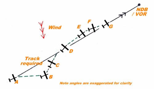
Tracking to an NDB
A useful ADF application in visual navigation is to locate a particular
NDB and then track
– or home – directly to it. The ADF receiver is tuned to the NDB frequency, and
the audio volume turned up, so that the NDB can be identified as soon as the
aircraft comes within range. The ADF needle indicates the bearing to the NDB and
the wind correction angle necessary to maintain that track is then ascertained
by bracketing, a technique which bears some similarity to the
double track error method. The
term 'bracketing' is derived from the artillery technique for ranging the target
by deliberately placing initial rounds behind and in front of it.
Note: this sequence is best performed if the heading being flown is positioned
on the ADF card at TDC, the diagrams in the left column below indicate the
readings with those settings.
procedure
| Needle position |
Compass heading |
Event sequence |
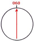 |
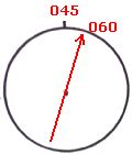
060° |
Position A. When receiving
the NDB signal turn the aircraft so that the head of the ADF needle is
pointing to TDC, then check the heading from the compass. That heading is
the track required to home directly to the NDB, for our example 060°
magnetic. Rotate the ADF compass card to set 060° at TDC and the needle
head will also indicate 060°. Remember that all heading changes should be
logged. |
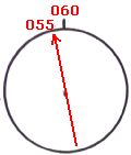 |
060° |
Position B. As the flight
progresses, holding the 060° heading, the crosswind causes the aircraft to
drift to the south of the required track and the ADF needle has moved left
about 5° to 055°. |
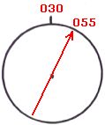 |
030° |
Position C. We now have to
make a first rough cut at the track error – it is best to initially
overestimate so let's choose 15° and, applying the double track error
technique, we turn left 30° on to an intercept heading of 030° magnetic.
Positioning the 030° heading at TDC, the head of the needle will still
initially indicate 055° but will move towards 060° as we close with the
required track. |
 |
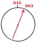
045° |
Position D. When the
needle reaches 060° the 060° track to the NDB has been regained. Now halve
the intercept angle (i.e. subtract the track error) and turn right onto an
initial wind correction heading of 045° magnetic, i.e. the estimated track
error was 15°, we turned left 30° onto the intercept heading of 030° and
now, having regained the required track, we turn right 15° onto a wind
correction heading of 045°.
Now rotate the card to the 045° heading and the needle remains at the 060°
bearing. |
 |
045° |
Position E. If the 15° WCA
is correct then the ADF needle will remain at the 015° position whilst the
045° heading is maintained. However it is most likely that we have
overcorrected, the aircraft will drift north of track, shown by the needle
moving clockwise a few degrees from the 015° position so we now have to
refine the wind correction angle. |
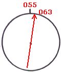 |
055° |
Position F. We might guess
that we have overestimated the WCA by about 5° so, applying the double
track error technique, we turn right 10° on to an intercept heading of
055° magnetic. Positioning the 055° heading at TDC, the head of the needle
will still initially indicate something greater than 060°, say 063°, but
will move towards 060° as we close with the required track. |
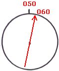 |
050° |
Position G. When the
needle reaches 060° the 060° track to the NDB has been regained. Now halve
the intercept angle and turn 5° left onto a wind correction heading of
050° magnetic, rotate the card to the 050° heading and, if we've estimated
correctly, the needle will remain at the 060° bearing, maintaining a 10°
WCA, while we continue along the required 060° track to the NDB.
|
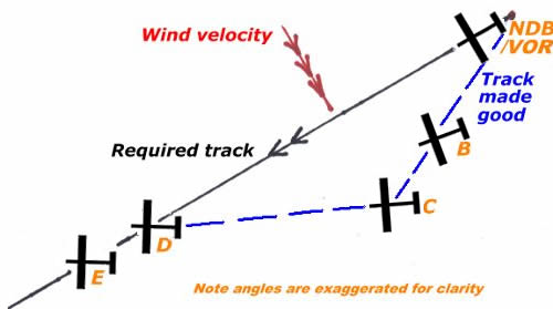
Tracking from an NDB
Another useful application for the ADF in visual navigation is in determining
track error when departing from an airfield equipped with an NDB or when
overflying an NDB.
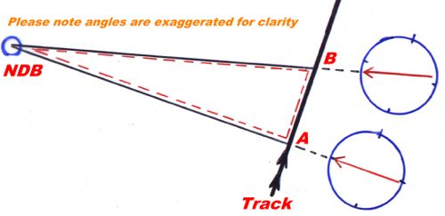
For example: the flight plan calls for a departure – from overhead an NDB – on a
track of 240° magnetic with any necessary wind correction to be assessed after
departure – using the ADF – with the track recovery and heading correction to be
made by a slightly modified
double track error method. (The modification is that rather than timing the
intercept leg to estimate track recovery we will use the ADF needle to indicate
when we are back over the required track.)
In this ADF application the ADF card may be used with the 0° position set at TDC
or your personal preference may be to set the 240° heading at TDC. The diagrams
and the text below indicate the procedure and the readings with 0° positioned at
TDC but the additional text in italics is the procedure when rotating the card
to the new heading for every change. Hopefully you will be able to see that the
latter method is easier to handle.
Note that when tracking away from an NDB we use the tail of the ADF needle,
rather than the head, as the indicator.
| Needle position |
Compass heading |
Event sequence |
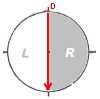 |
240° |
Departing from overhead
the NDB to track 240° magnetic.
The magnetic compass heading is 240° ( i.e. no wind correction provision)
and the tail of the ADF needle swings to the 0° position.
With the 240° magnetic heading set
at TDC the position of the needle relative to TDC is exactly the same as
in the diagram but, on the background card, the needle tail indicates the
240° heading. |
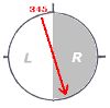 |
240° |
Position B. As the flight
progresses holding the 240° heading the crosswind causes the aircraft to
drift to the south of the required track.
The tail of the ADF needle has moved about 15° to 345° and is in the left
half of the card. Thus the opening angle, or track error, is 15° and the
tail of the needle represents the track made good, which is 15° to the
left of the required track.
With the 240° magnetic heading set
at TDC the tail of the needle will indicate the track made good, 225° or
an opening angle, or track error, of 15°. |
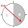 |
270° |
Position C. Use the double
track error method to intercept the required track.
The aircraft is turned 30° [2 × 15] onto a heading of 270° magnetic. The
ADF needle tail initially moves 30° to 315° then commences to reverse
direction as the 270° heading is maintained and the aircraft is closing
the 240° track out.
The aircraft is turned 30° [2 × 15] onto a heading of 270° magnetic and
270° magnetic is now set at TDC, the tail of the needle will then
initially still indicate 225° but will move towards 240° as you close with
the required track. |
 |
270° |
Position D. When the
needle has moved through a 15° arc and is back to the 30° left position
[330°], on a heading of 270°, the 240° track out from the NDB has been
regained.
With the 270° magnetic heading set at TDC the 240° track out from the
NDB has been regained when the tail of the needle reaches 240°.
|
 |
255° |
Position E. Subtract the
track error [15°] and turn left onto the new heading of 255° which will
then maintain the necessary 15° wind correction angle.
The ADF needle moves 15° clockwise and the aircraft should hold the
required track – if the heading is maintained and the needle kept at the
345° position.
Subtract the track error [15°] and turn left onto the new heading of
255° which will then maintain the necessary 15° wind correction angle. Set
the 255° magnetic heading at TDC, the tail of the needle now indicates
255°.
After flying this heading for a while you may find that you still have
some drift – indicated by movement of the needle. In this case a small
heading correction is usually enough compensation. |
Running
fix / distance from NDB
Whenever your track will pass abeam an NDB it is quite easy
to obtain a running fix, using the 1-in-60 rule and a little mental arithmetic,
providing you have a reasonable idea of your groundspeed. The technique is
illustrated in the diagram:
Procedure
1. Tune and identify the NDB, set your heading at TDC and
watch the ADF needle, the NDB is directly abeam when it moves to 90° either side
of TDC, position A in the diagram.
2. Note the time and continue flying your heading, for example 040° magnetic.
3. When the needle has moved a sufficient amount to get a good reading (position
B on the diagram), note the time and the bearing from the NDB, indicated by the
tail of the needle. Let's say the needle has moved 10°, the elapsed time is 8
minutes, the bearing from the NDB is 110° magnetic and you reckon your
groundspeed at 70 knots.
4. Now we calculate the distance we are along that bearing using the 1-in-60
rule:
i.e the distance [nm] from the NDB = elapsed time [minutes] × ground speed
[knots] / degrees traversed = 8 × 70/10 = 56 nm. The aircraft's position at time
B is then 110°/56 nm from the NDB. The real difficulty now is to measure and
plot that position on the navigation chart whilst flying the aircraft (not
forgetting to convert the bearing to °true) – so best to get the passenger to do
it.
If you are wondering what happened to the '60' in the 1-in-60 application the
answer is it is negated by the usage of minutes in one factor and nautical miles
per hour in another. In the diagram the dashed red line outlines the right angle
triangle on which the calculation is based – the distance from the NDB to
position B forms the hypotenuse.
ADF applications
There are several applications for the ADF in light aircraft
cross country VMC navigation – remembering the Visual Flight Rules require that
the pilot must be able to navigate by reference to the ground and position fixes
must be taken at least every 30 minutes.
Position fixes. If two (or better - three) transmitters are in range then the
bearing from each can be ascertained, the lines of position roughly plotted on
the chart (after converting to true bearings) and the aircraft position will be
close to the intersection point. In most of Australia to have two NDBs in range
at the same time is not so common and three would be most unlikely, so the most
likely position fixing use is to combine a surface line feature with an NDB
bearing.
Running fix / distance from NDB. The 1-in-60 rule can be applied when the
aircraft is within range of a transmitter by turning the aircraft so that the
station is abeam and then measuring the degrees traversed against time. This is
a form of running fix in that two bearings are taken, at an interval, from one
source and the aircraft's position is the distance along the second LOP from the
NDB. For example:
Distance [nm] to NDB = elapsed time [minutes] × ground speed [knots] / degrees
traversed
Homing & tracking to or from an NDB. If there is no crosswind component then
tracking toward an NDB is quite simple, just keep the head of the ADF needle at
TDC and you will arrive overhead; the track over the ground will be straight and
the magnetic heading consistent. However if there is a crosswind component and
you just endeavour to keep the head of the ADF needle at TDC, you will
eventually arrive but, due to the drift, the track followed will be curved and
the magnetic heading will need to be consistently changing. This is called
homing, and you will arrive at the NDB on an into-wind heading. Thus tracking,
or flying directly towards, or from, an NDB is exactly the same as tracking from
A to B – you have to calculate a wind correction angle. Passage overhead an NDB
is signified by a "cone of silence" (if the ident volume has been turned up
beforehand) and the needle then swinging to the reciprocal bearing.
Using the ADF probably appears to be fairly simple, which it is, but there will
be difficulties, for the uninitiated in perceiving, from the position of the
needle, the headings to fly when attempting to intercept and then track along a
particular magnetic bearing to or from the ground station.
As in all navigation you should always maintain an awareness of the aircraft's
position in terms of being north, south, east or west of the NDB and, when
initiating a turn, think in the same terms e.g. a left turn will take you
further east.
NDB/ADF errors
Electrical interference. Radio waves are emitted by the aircraft alternator in
the frequency band of the ADF. An alternator suppressor is fitted to contain
those emissions but this component does not have a long life and it is wise to
test the ADF for correct operation during pre-flight checks. The test is made by
selecting a transmitter – which must be a reasonable distance away, say 30 nm –
then watch the ADF needle during the engine run up. If the needle moves as rpm
increase there is electrical interference and probably the alternator suppressor
should be replaced. Magnetos may also interfere with the ADF.
Thunderstorms emit electrical energy in the NDB band and will deflect the ADF
needle towards the storm.
Twilight/night effect. Radio waves arriving at a receiver come both directly
from the transmitter – the ground wave – and indirectly as a wave reflected from
the ionosphere – the sky wave. The sky wave is affected by the daily changes in
the ionosphere, read the ionisation layers section in the Aviation Meteorology
Guide. Twilight effect is minimal on transmissions at frequencies below 350 kHz.
Terrain and coastal effects. In mountainous areas NDB signals may be reflected
by the terrain which can cause the bearing indications to fluctuate. Some NDBs
located in conditions where mountain effect is troublesome transmit at the
higher frequency of 1655 kHz. Ground waves are refracted when passing across
coast lines at low angles and this will affect the indicated bearing for an
aircraft tracking to seaward and following the shore line.
Attitude effects. The indicated bearing will not be accurate whilst the aircraft
is banked.
