
radio navigation (an overview)
Low frequencies were very important to air navigation years ago, but became
increasingly less important as more reliable systems operating at higher
frequencies were developed and became widely available. Many Low Frequency
navigation beacons were decommissioned long ago because of that. The few that
remain primarily provide backup navigation in the event of primary navigation
system failures, although some are used routinely even today in the execution of
instrument landings.
Long ago, before VHF Omnirange (VOR)
and other superior navigation systems were developed, that band contained AN
Radio Ranges and Non-Directional Beacons (NDB's). 344 AN Radio Ranges still
existed in the United States in 1959, but none exist today. Some NDB's are all
that remain.
The Low Frequency (LF) aviation
band extends from 200 kHz to 415 kHz with some internal gaps assigned to other
services. The entire Low Frequency (LF) aviation band can be received by the
receiver at this website.
Medium Frequency Aviation Band Usage
The only portion of the Medium Frequency spectrum allocated for aviation use is
the 2850 to 3000 kHz portion of the 2850 to 3155 kHz Aviation Band. However,
most aircraft are equipped with radio direction finders than can receive Medium
Frequency AM Broadcast Band.
High Frequency (HF) Aviation Bands
High Frequencies were widely used for domestic aircraft voice communications
years ago. Nearly all that traffic moved to Very High Frequencies long ago and
domestic aircraft use of Medium Frequencies is now very rare. However,
international flights still use the High Frequencies bands routinely for voice
communications, because of the much longer distances over which they can be
used.
Radio
navigation provides the pilot with position information from ground stations
located worldwide. There are several systems offering various levels of
capability with features such as course correction information, automatic
direction finder and distance measuring.
Most aircraft now are equipped with some type of radio navigation equipment.
Almost all flights whether cross-country or "around the patch" use radio
navigation equipment in some way as a primary or secondary navigation aid.
|
Table of Radio Frequencies |
|
Description |
Abbreviation |
Frequency |
Wavelength |
|
Very Low Frequency |
VLF |
3 KHz - 30 KHz |
100,000m - 10,000m |
|
Low Frequency |
LF |
30 KHz - 300 KHz |
10,000m - 1,000 |
|
Medium Frequency |
MF |
300 KHz - 3 MHz |
1,000m - 100m |
|
High Frequency |
HF |
3 MHz - 30 MHz |
100m - 10m |
|
Very High Frequency |
VHF |
30 MHz - 300 MHz |
10m - 1m |
|
Ultra High Frequency |
UHF |
300 MHz - 3 GHz |
1m - 0.10m |
|
Super High Frequency |
SHF |
3 GHz - 30 GHz |
0.10m - 0.01m |
|
Extremely High Frequency |
EHF |
30 GHz - 300 GHz |
0.01m - 0.001m |
The fact
that radio signals can travel all over the globe on the HF bands is widely
used from radio hams to broadcasters and maritime applications to diplomatic
services. Radio transmitters using relatively low powers can be used to
communicate to the other side of the globe. Although this form of
communication is not as reliable as satellites, radio hams enjoy the
possibility of making these contacts when they occur. Other users need to be
able to establish more reliable communications. In doing this they make
extensive use of propagation programmes to predict the regions to which
signals will travel, or the probability of them reaching a given area.
These propagation prediction programmes utilise a large amount of data, and
many have been developed over many years. However it is still useful to gain a
view of how signals travel on these frequencies, to understand why signal
conditions change and how the signals propagate at these frequencies.
Radio signals in the medium and short wave bands travel by two basic means.
The first is known as a ground wave, and the second a sky wave.
Ground Wave
Ground wave radio propagation is used mainly on the medium wave band. It might
be expected that the signal would travel out in a straight line. However it is
affected by the proximity of the earth it is found that the signal tends to
follow the earth's curvature. This occurs because currents are induced in the
surface of the earth and this slows down the wave front close to the ground.
This results in the wave front tilting downward, enabling it to follow the
curvature of the earth and travel beyond the horizon.
Ground
wave propagation
Ground wave propagation becomes less effective as the frequency rises. The
distances over which signals can be heard steadily reduce as the frequency
rises, to the extent that even high power short wave stations may only be
heard over a few kilometres via this mode of propagation. Accordingly it is
only used for signals below about 2 or 3 MHz. In comparison medium wave
stations are audible over much greater distances - typically the coverage area
for a high power broadcast station may extend out a hundred kilometres or
more. The actual coverage is affected by a variety of factors including the
transmitter power, the type of antenna, and the terrain over which the signal
is travelling.
Signals also leave the earth's surface and travel towards the ionosphere, some
of these are returned to earth. These signals are termed sky waves for obvious
reason.
D layer
When a sky wave leaves the earth's surface and travels upwards, the first
layer of interest that it reaches in the ionosphere is called the D layer.
This layer attenuates the signals as they pass through. The level of
attenuation depends on the frequency. Low frequencies are attenuated more than
higher ones. In fact it is found that the attenuation varies as the inverse
square of the frequency, i.e. doubling the frequency reduces the level of
attenuation by a factor of four. This means that low frequency signals are
often prevented from reaching the higher layers, except at night when the
layer disappears.
The D layer attenuates signals because the radio signals cause the free
electrons in the layer to vibrate. As they vibrate the electrons collide with
molecules, and at each collision there is a small loss of energy. With
countless millions of electrons vibrating, the amount of energy loss becomes
noticeable and manifests itself as a reduction in the overall signal level.
The amount of signal loss is dependent upon a number of factors: One is the
number of gas molecules that are present. The greater the number of gas
molecules, the higher the number of collisions and hence the higher the
attenuation. The level of ionisation is also very important. The higher the
level of ionisation, the greater the number of electrons that vibrate and
collide with molecules. The third main factor is the frequency of the signal.
As the frequency increases, the wavelength of the vibration shortens, and the
number of collisions between the free electrons and gas molecules decreases.
As a result signals lower in the frequency spectrum are attenuated far more
than those which are higher in frequency. Even so high frequency signals still
suffer some reduction in signal strength.
E and F Layers
Once a signal passes through the D layer, it travels on and reaches first the
E, and next the F layers. At the altitude where these layers are found the air
density is very much less, and this means that when the free electrons are
excited by radio signals and vibrate, far fewer collisions occur. As a result
the way in which these layers act is somewhat different. The electrons are
again set in motion by the radio signal, but they tend to re-radiate it. As
the signal is travelling in an area where the density of electrons is
increasing, the further it progresses into the layer, the signal is refracted
away from the area of higher electron density. In the case of HF signals, this
refraction is often sufficient to bend them back to earth. In effect it
appears that the layer has "reflected" the signal.
The tendency for this reflection is dependent upon the frequency and the angle
of incidence. As the frequency increases, it is found that the amount of
refraction decreases until a frequency is reached where the signals pass
through the layer and on to the next. Eventually a point is reached where the
signal passes through all the layers and on into outer space.
Refraction of a signal as it enters an ionised layer
Different frequencies
To gain a better idea of how the ionosphere acts on radio signals it is worth
viewing what happens to a signal if the frequency is increased across the
frequency spectrum. First it starts with a signal in the medium wave broadcast
band. During the day signals on these frequencies only propagate using the
ground wave. Any signals that reach the D layer are absorbed. However at night
as the D layer disappears signals reach the other layers and may be heard over
much greater distances.
If the frequency of the signal is increased, a point is reached where the
signal starts to penetrate the D layer and signals reach the E layer. Here it
is reflected and will pass back through the D layer and return to earth a
considerable distance away from the transmitter.
As the frequency is increased further the signal is refracted less and less by
the E layer and eventually it passes right through. It then reaches the F1
layer and here it may be reflected passing back through the D and E layers to
reach the earth again. As the F1 layer is higher than the E layer the distance
reached will be greater than that for an E layer reflection.
Finally as the frequency rises still further the signal will eventually pass
through the F1 layer and onto the F2 layer. This is the highest of the layers
reflecting layers in the ionosphere and the distances reached using this are
the greatest. As a rough guide the maximum skip distance for the E layer is
around 2500 km and 5000 km for the F2 layer.
Signals
reflected by the E and F layers
Multiple hops
Whilst it is possible to reach considerable distances using the F layer as
already described, on its own this does not explain the fact that signals are
regularly heard from opposite sides of the globe. This occurs because the
signals are able to undergo several reflections. Once the signals are returned
to earth from the ionosphere, they are reflected back upwards by the earth's
surface, and again they are able to undergo another reflection by the
ionosphere. Naturally the signal is reduced in strength at each reflection,
and it is also found that different areas of the earth reflect radio signals
differently. As might be anticipated the surface of the sea is a very good
reflector, whereas desert areas are very poor. This means that signals that
are reflected back to the ionosphere by the Pacific or Atlantic oceans will be
stronger than those that use the Sahara desert or the red centre of Australia.
Multiple reflections
It is not just the earth's surface that introduces losses into the signal
path. In fact the major cause of loss is the D layer, even for frequencies
high up into the HF portion of the spectrum. One of the reasons for this is
that the signal has to pass through the D layer twice for every reflection by
the ionosphere. This means that to get the best signal strengths it is
necessary signal paths enable the minimum number of hops to be used. This is
generally achieved using frequencies close to the maximum frequencies that can
support ionospheric communications, and thereby using the highest layers in
the ionosphere. In addition to this the level of attenuation introduced by the
D layer is also reduced. This means that a signal on 20 MHz for example will
be stronger than one on 10 MHz if propagation can be supported at both
frequencies.
A VOR is a Very-high-frequency
OmniRange radio transmitter. VORs constitute the backbone of current land-based
aerial navigation in the U.S. and Western Europe. But first, let's start with
the NDB because it's a simpler device.
NDB
An NDB (Non-Directional
Beacon) is a radio beacon that broadcasts continuously on a specific
frequency. Aircraft on-board radio equipment can determine in which direction
from the aircraft an NDB signal is coming. The on-board aerial consists of a
simple metal loop which is rotatable. The radio signal induces a current in the
loop, as in a normal aerial, but this current is weaker or stronger depending on
the orientation of the loop. When the loop is flat-on to the origin of the
signal, the signal is strongest. (Think of the loop as the frame of a round
mirror. The signal is detected to be strongest when the mirror is reflecting it
back at itself.) The official definition is
A L/MF [low- or
medium-frequency] or UHF [ultra-high-frequency] radio beacon transmitting
non-directional signals whereby the pilot of an aircraft equipped with
direction finding equipment can determine his bearing to or from the radio
beacon and "home" on or track from the station. When the radio beacon is
installed in conjunction with the Instrument Landing System marker, it is
normally called a Compass Locator.,
in which bearing means:
The horizontal direction to
or from any point, usually measured clockwise from true north, magnetic north,
or some other reference point through 360 degrees.
Because aircraft can determine
from which direction the signal is coming, they can `home in on', fly in the
direction of, the signal to arrive at the beacon.
NDBs broadcast in the frequency
band of 190 to 535kHz (a `Hertz', Hz, is one cycle per second) and transmit a
continuous carrier signal with either 400 or 1020 Hz modulation. An
identification signal consisting of three letters in Morse code is also
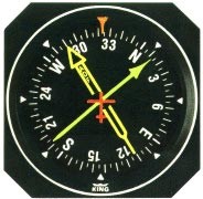
transmitted. The receiver equipment in the airplane is called an ADF (`Automatic
Direction Finder'). The indicator consists of a round calibrated dial and a
`needle' pointer which points in the direction that the signal is determined to
be coming from.
There are two problems with NDBs.
First, erroneous signals.
Radio beacons are subject
to disturbances that may result in erroneous bearing information. Such
disturbances result from such factors as lightning, precipitation static, etc.
At night radio beacons are vulnerable to interference from distant stations.
Noisy identification usually occurs when the ADF needle is erratic. Voice,
music or erroneous identification may be heard when a steady false bearing is
being displayed. Since ADF receivers do not have a "flag" to warn the pilot
when erroneous bearing information is being displayed, the pilot should
continuously monitor the NDB's identification.
Second, you can only tell the
relative bearing of your aircraft to the NDB - that is, the direction in
which the NDB lies. Only by comparing this against the aircraft compass heading
(as stably indicated by the directional gyroscope) and doing some trivial
trigonometry in his/her head can a pilot determine at which (magnetic or true)
bearing the NDB lies from the aircraft. This can be illustrated thus:
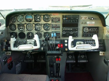
The circular black dial with
indicator in the middle of the aircraft is what the pilot sees inside the
aircraft.
Some aircraft have an instrument
called an RMI (Radio Magnetic Indicator) which incorporates both a
directional gyro and the ADF needle so that one can read the magnetic bearing to
the beacon directly off the instrument without having to do mental trigonometry.
The service range of an
NDB is the distance from the NDB within which a reliable signal is guaranteed.
Service ranges are classified as 15, 25, 50 and 75 nautical miles.
NDB Navigation
NDB navigation is not
necessarily easy. First, there is a course to be flown. Second, the aircraft may
be on-course or slightly (or hugely) off-course. Thirdly, the heading of the
aircraft may be different from track, to accommodate a crosswind. During an
instrument approach, a pilot has to continuously determine all this information,
and also calculate and fly corrections. Determining which heading to hold to
accommodate a crosswind is an empirical matter. One guesses a heading and
determines drift (range of divergence of track from course) and then corrects -
first twice as much, to get back onto course, and then when back on course,
enough to follow course. All this is quite tricky and one needs to be in
practice. This is crucial when flying an instrument approach, since strict
adherence to course and altitude restrictions are the only things that guarantee
that the aircraft flies clear of obstacles. Anybody who has flown an NDB
instrument approach to an airport runway knows how labour-intensive it is. One
has to achieve course-following using the above procedure, correcting for
probably-changing crosswinds as one descends in altitude, especially in
non-level terrain, very accurately and all inside of 2 or 3 minutes.
Use of an ADF in NDB navigation
can be illustrated thus:
The aircraft is flying on a
course directly from the beacon. We don't know what azimuth this course has, but
the dial on the ADF is set to straight-ahead=0° (on an RMI, there would be a
directional gyro indicator here, not a settable dial). There is a crosswind
coming from the left, so a heading correction to the left of 030° must be taken
to maintain course in the crosswind. This heading correction shows up on the ADF,
indicating that the beacon is relatively at a bearing of 210° behind the
aircraft, which means with the heading correction for crosswind, that we are
flying on a course with the beacon at a bearing of 180° to our course behind us.
The solution to NDB navigation
problems is the VOR.
VORs
VHF Omni-directional Radio (VORs)
are radio beacons that transmit an signal which contains precise azimuth
information, so that upon reception of the signal, an aircraft can tell
precisely what bearing with respect to magnetic north the station is from the
aircraft (respectively, on what radial the aircraft lies from the station - this
is just the reciprocal of the bearing to the station from the aircraft). Such a
signal has the advantage that the bearing to the station is read directly off
the indicator equipment. `The accuracy of course alignment of the VOR is
excellent, being generally plus or minus 1 degree'
Navigating on VOR information is
akin to flying on a grid such as the following:
Here, the aircraft is positioned
directly on the 315° radial from the VOR. (We do not know on what course the
aircraft is flying, although its heading appears to be about 350°.)
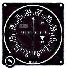
Besides being very accurate, the
VOR is much easier to use than an NDB. The indicator in the cockpit is a round
dial with settable azimuth information, called the Omni Bearing Selector
(OBS) and a vertical pendulum-like needle, called the Course Deviation
Indicator (CDI) thus:
When the aircraft is on the
radial set on the instrument (actually, one can set either bearing or radial,
depending on which is more meaningful in the situation), the needle points
vertically down. When the aircraft has deviated from course, the needle will
deviate sideways. A series of dots is shown on the instrument dial so that one
can tell how much deviation: `one dot', `two dots', `three dots', `four dots'. A
dot is equal to about 2° of deviation. This means that at a distance of 60
nautical miles from the VOR, a one-dot deviation on the CDI indicates that the
aircraft is about 2 nautical miles from the selected radial. At 30 nautical
miles, one dot would indicate 1 NM of deviation, and so on. When the aircraft is
left of course, the CDI needle will deviate to the right, showing the pilot
which direction the desired course lies. Similarly, when right of course, the
CDI needle will indicate to the left, as in this illustration:
In this diagram, the OBS is set
to 0°=360°. An aircraft in position A, B, or C will show a deviation on the CDI
as shown to the right (but somewhat exaggerated - the precise number of dots
shows a 4° deviation, and the positions A, B, C are indicated much more than 4°
to the right of course). Aircraft with 0° set in the OBS, to the south of the
VOR in positions D and E, will show a similar deviation. It is important to
realise that, unlike with an ADF display, the VOR indicator (OBS and CDI) shows
position over the ground with respect to the VOR, and independent of
heading or course.
Thus position information along
a radial from a VOR is shown directly and accurately on the VOR indicator and
there is no need to follow the complicated procedures involved in NDB
navigation. One can determine absolute position by tuning two VOR receivers to
two different VORs, determining (by centring both DCIs) on what radial from each
VOR the aircraft currently lies, and then drawing these two extended radials on
the chart on one's knee (the radials are shown on the chart for each VOR, but
they don't extend very far from the VOR) to see where they intersect, and that's
where the aircraft is!
There are some devices called
RNAV which integrate such information from two or more VORs to construct a
`virtual VOR' on any chosen course, so that to fly this course, one just centres
the CDI needle on the indicator, as though there were actually a VOR one is
flying towards. RNAVs are nice.
VOR navigation is the major
navigation technique throughout much of the world, and certainly in developed
countries such as the U.S. and Western Europe. It was developed a half-century
ago, after the Second World War.
Technically, VOR operation is
achieved by transmitting two signals (actually, there is a continuous carrier
with modulation, but let us for the moment consider it as a discrete signal).
The base signal is transmitted at regular intervals, let us say time interval
T, and in between base signals occurs an azimuth signal. The difference in
time between base signal and azimuth signal determines the radial azimuth (from
magnetic north) from the VOR that the aircraft is on. When the aircraft is due
(magnetic) north of the VOR, the two signals coincide. As the radial angle
increases clockwise, the signals become further and further apart. For example,
at 90°, the azimuth signal will be at 0.25T; at 180°, at 0.5T; at
270°, 0.75T, until when at magnetic north again, the two signals again
coincide.
VOR reception is line-of-sight.
`VORs operate within the 108.0 to 117.95 MHz frequency band, and have a power
output necessary to provide coverage within their assigned operational service
volume'. The service volumes are given by the class of VOR:
-
T (Terminal): From 1000 feet
above ground level (AGL) up to and including 12,000 feet AGL at radial
distances out to 25 NM;
-
L (Low Altitude): From 1000 ft
AGl up to and including 18,000 feet AGL at radial distances out to 40 NM;
-
H (High Altitude): From 1000
feet AGL up to and including 14,500 feet AGL at radial distances out to 40 NM.
From 14,500 AGL up to and including 60,000 feet at radial distances out to 100
NM. From 18,000 feet AGL up to and including 45,000 feet AGL at radial
distances out to 130 NM.
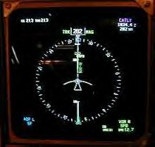
Finally, many aircraft (and most
commercial transports) have an instrument that combines a directional gyroscope
with a VOR receiver, called a Horizontal Situation Indicator (HSI) and
which looks like this:
Instrument Landing System (ILS)
An aircraft on an instrument
landing approach has a cockpit with computerized instrument landing equipment
that receives and interprets signals being from strategically placed stations on
the ground near the runway. This system includes a "Localizer" beam that uses
the VOR indicator with only one radial aligned with the runway. The Localizer
beam's width is from 3° to 6°. It also uses a second beam called a "glide slope"
beam that gives vertical information to the pilot. The glide slope is usually 3°
wide with a height of 1.4°. A horizontal needle on the VOR/ILS head indicates
the aircraft's vertical position. Three marker beacons (outer, middle and inner)
are located in front of the landing runway and indicate their distances from the
runway threshold. The Outer Marker (OM) is 4 to 7 miles from the runway. The
Middle Marker (MM) is located about 3,000 feet from the landing threshold, and
the Inner Marker (IM) is located between the middle marker and the runway
threshold where the landing aircraft would be 100 feet above the runway.
The VOR indicator for an ILS system uses a horizontal needle in addition to the
vertical needle. When the appropriate ILS frequency is entered into the
navigation radio, the horizontal needle indicates where the aircraft is in
relation to the glide slope. If the needle is above the centre mark on the dial,
the aircraft is below the glide slope. If the needle is below the centre mark on
the dial, the aircraft is above the glide slope.
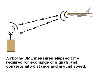
Distance Measuring
Equipment (DME)
DME as its name states is an electronic device that measures "slant range" from
the DME station. Slant range is a measure of an aircraft's position relative to
the DME station that incorporates the height of the aircraft, its angle from the
ground station and its unknown ground range based upon a 90° angle. The farther
the aircraft is from the station and the lower the aircraft's altitude, the more
accurate the distance reading. An aircraft could be directly over the DME
station at an altitude of 10,500 feet above ground level (AGL) and the DME would
correctly indicate the aircraft is two miles from the station.
Marker Beacons
1.
ILS marker beacons have a rated power output of 3 watts or less and an antenna
array designed to produce an elliptical pattern with dimensions, at 1,000 feet
above the antenna, of approximately 2,400 feet in width and 4,200 feet in
length. Airborne marker beacon receivers with a selective sensitivity feature
should always be operated in the "low" sensitivity position for proper
reception of ILS marker beacons.
2.
Ordinarily, there are two marker beacons associated with an ILS, the OM and
MM. Locations with a Category II and III ILS also have an Inner Marker (IM).
When an aircraft passes over a marker, the pilot will receive the following
indications: (See Table 1-10[1]).
| MARKER |
CODE |
LIGHT |
| OM |
--- |
BLUE |
| MM |
.-.- |
AMBER |
| IM |
.... |
WHITE |
| BC |
.. .. |
WHITE |
Table 1-10[1]
-
(a) The OM normally
indicates a position at which an aircraft at the appropriate altitude on the
localizer course will intercept the ILS glide path.
-
(b) The MM indicates a
position approximately 3,500 feet from the landing threshold. This is also
the position where an aircraft on the glide path will be at an altitude of
approximately 200 feet above the elevation of the touchdown zone.
-
(c) The inner marker (IM)
wll indicate a point at which an aircraft is at a designated decision height
(DH) n the glide path between the MM and landing threshold.
Global Positioning System (GPS)
GPS receivers cost thousands of
dollars in 1990, but are available now for under $100 for simple hand held
units. Aircraft GPS units designed for IFR flight still cost thousands of
dollars each, but many General Aviation (GA) pilots now fly with a low cost hand
held GPS receiver.
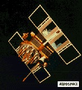
The GPS system uses a constellation of 24 or more satellites, 21 plus
spares, at an altitude of 10,900 miles, moving 7,500 nmph. Two UHF frequencies,
1.57542 gHz and 1.22760 gHz are used. Ionospheric distortion is measured by the
phase shift between the two frequencies.

Two modes are available, the "P", or precise mode, and the "C/A" or
Coarse/Acquisition Mode. The P mode used by the military transmits a
pseudo-random pattern at a rate of 10,230,000 bits/sec and takes a week to
repeat. The C/A code is 10 times slower and repeats every
millisecond.
The GPS receiver synchronizes itself with the satellite code
and measures the elapsed time since transmission by comparing the difference
between the satellite code and the receiver code. The greater the difference,
the greater the time since transmission. Knowing the time and the speed of
light/radio, the distance can be calculated.
The timing comes from four atomic clocks on each satellite.
The clocks are accurate to within 0.003 seconds per thousand years. The GPS
satellites correct for receiver error, by updating the GPS receiver clock. The
GPS satellite also transmits its position, its ephemeris, to the GPS receiver so
it knows where it is relative to the satellite. Using information from four or
more satellites the GPS receiver calculates latitude, longitude, and altitude.
(The math involves matrix algebra and the solution of simultaneous equations
with four unknowns. Computers do that sort of computation very well.)
GPS receivers provide all needed navigational information
including:
 Bearing
Range
Track
Ground speed
Estimated time en route (ETE)
Cross track error
Track angle error
Desired track
Winds & drift angle
Differential GPS or DGPS
DGPS uses a ground station to correct
the code received from the satellites for 5 meter accuracy. DGPS could be used
for Precision approaches to any airport.
|
