helicopters:
their main components and
controls
with thanks to the
helicopterpage
Rotary Wing
Terminology
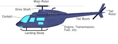
Most helicopters the engine
turns a shaft that connects to an input quill
on the transmission; the main rotor mast comes
straight out of the top of the transmission
and the tailrotor driveshaft connects to an
output quill 90 degrees out from the mast.
Spinning the rotor which has an aerofoil
section causes
lift, allowing the helicopter to rise
vertically or hover.
Tilting the spinning rotor will cause flight
in the direction of the tilt.
There are many terms
associated with rotary wing flight and it is
important for a student to become familiar
with them to understand the mechanics of rotary wing
flight.
Main Rotor
System
 Root: The
inner end of the blade where the rotors
connect to the blade grips.
Root: The
inner end of the blade where the rotors
connect to the blade grips.
Blade
Grips: Large attaching points where the
rotor blade connects to the hub.
Hub: Sits
atop the mast, and connects the rotor blades
to the control tubes.
Mast:
Rotating shaft from the transmission, which
connects the rotor blades to the helicopter.
Control
Tubes: Push \ Pull tubes that change the
pitch of the rotor blades.
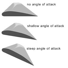
Pitch
Change Horn: The armature that converts
control tube movement to blade pitch.
Pitch:
Increased or decreased angle of the rotor
blades to raise, lower, or change the
direction of the rotors thrust force.
Jesus Nut:
Is the singular nut that holds the hub onto
the mast. (If it fails, the next person you
see will be Jesus).
this type of rotor system pivots around the
trunion to allow for blade flapping
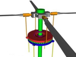
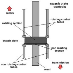
Swash plate
The swash plate assembly has two primary
roles:
Under the direction of the collective
control, the swash plate assembly can change
the angle of both blades simultaneously.
Doing this increases or decreases the lift
that the main rotor supplies to the vehicle,
allowing the helicopter to gain or lose
altitude.
Under the direction of the cyclic
control, the swash plate assembly can change
the angle of the blades individually as they
revolve. This allows the helicopter to move
in any direction around a 360-degree circle,
including forward, backward, left and right.
The swash plate assembly consists of two
plates -- the fixed and the rotating
swash plates -- shown above in blue and red,
respectively.
The rotating swash plate rotates
with the drive shaft (green) and the rotor's
blades (grey) because of the links (purple)
that connect the rotating plate to the drive
shaft.
The pitch control rods (orange)
allow the rotating swash plate to change the
pitch of the rotor blades.
The angle of the fixed swash plate
is changed by the control rods (yellow)
attached to the fixed swash plate.
The fixed plate's control rods are
affected by the pilot's input to the cyclic and collective controls.
The fixed and rotating swash plates are
connected with a set of bearings
between the two plates. These bearings allow
the rotating swash plate to spin on top of
the fixed swash plate.
Controls
Collective: The
up and down control. It puts a collective
control input into the rotor system, meaning
that it puts either "all up", or "all down"
control inputs in at one time through the
swash plate. It is operated by the stick on
the left side of the seat, called the
collective pitch control. It is operated by
the pilots left hand.
The collective
lets you change the angle of attack of the
main rotor simultaneously on both blades.
Cyclic: The
left and right, forward and aft control. It
puts in one control input into the rotor
system at a time through the swash plate. It
is also known as the "Stick". It comes out
of the centre of the floor of the cockpit,
and sits between the pilots legs. It is
operated by the pilots right hand.
The cyclic changes the angle
of attack of the main rotor's wings unevenly
by tilting the swash plate assembly. On one
side of the helicopter, the angle of attack
(and therefore the lift) is greater.
Pedals: These
are not rudder pedals, although they are in
the same place as rudder pedals on an
airplane. A single rotor helicopter has no
real rudder. It has instead, an anti-torque
rotor (Also known as a tail rotor), which is
responsible for directional control at a
hover, and aircraft trim in forward flight.
The pedals are operated by the pilots feet,
just like airplane rudder pedals are. Tandem
rotor helicopters also have these pedals,
but they operate both main rotor systems for
directional control at a hover.
The Tail Rotor
The tail
rotor is very important. If you spin a rotor
using an engine, the rotor will rotate, but
the engine and the helicopter will try to
rotate in the opposite direction. This is
called TORQUE REACTION
The tail rotor is used like
a small propeller, to pull against torque
reaction and hold the helicopter straight.
By applying more or less
pitch (angle) to the tail rotor blades it can
be used to make the helicopter turn left or
right, becoming a rudder. The tail rotor is
connected to the main rotor through a gearbox.
When using the tail rotor trying to compensate
the torque, the result is an excess of force
in the direction for which the tail rotor is
meant to compensate, which will tend to make
the helicopter drift sideways.
Pilots tend to compensate by applying a little
cyclic pitch, but designers also help the
situation by setting up the control rigging to
compensate.
The result is that many helicopters tend to
lean to one side in the hover and often touch
down consistently on one wheel first.
On the other hand if you observe a hovering
helicopter head-on you will often note that
the rotor is slightly tilted. All this is a
manifestation of the drift phenomenon.
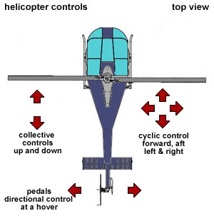
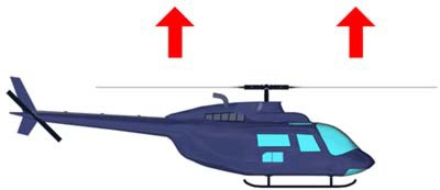
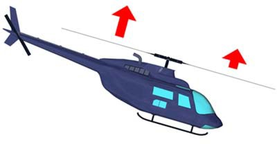
This picture
illustrates how the helicopter moves when
using the appropriate controls. Up and Down
movements are controlled by the "Collective".
Side to Side and Forward and Back motions are
controlled by the "Cyclic". Lateral control
(Also called directional control or "Yaw") is
achieved by using the "Foot Pedals".
Dissymmetry of
lift
One
cannot begin to talk about the mechanics of
helicopters until the problems
associated with rotary wing aerodynamics are
understood. When
the first rotary wing pioneers started trying
to make a helicopter fly, they noticed a
strange problem.
The helicopters
rotor system would generally work just fine
until one of two things happened: Either the
aircraft began to move in any given direction,
or it experienced any sort of wind introduced
into the main rotor system. Upon either of
these events, the rotor system would become
unstable, and the resultant crash would
usually take the life of the brave soul at the
controls. The question then was; Why does this
happen? The answer is what we refer to today
as "Dissymmetry of lift".
What "Dis-Symmetry
of lift" means is, when the rotor system is
experiencing the same conditions all around
the perimeter of the rotors arc, all things
are equal, and the system is in balance. Once
the system experiences a differential in wind
speed from any angle, it becomes unbalanced,
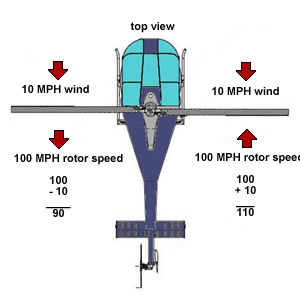
and begins to rotate. Take for instance
forward flight. Imagine a two bladed rotor
system spinning at 100 MPH.
The blade moving
toward the forward end of the aircraft is
going 100 MPH forward, and the blade moving
toward the back of the aircraft is travelling
at 100 MPH in the other direction. This is
just fine when the aircraft is not moving or
is in a no wind condition. It is experiencing
100 MPH of wind in all directions, so it is
totally in balance. Once the aircraft moves
forward, it begins to change this balance. If
we travel 10 MPH forward, then the forward
moving, or advancing rotor blade, is
experiencing 110 MPH of wind speed, and the
rearward, or retreating blade, is experiencing
only 90 MPH of wind speed.
When this happens,
we get an unbalanced condition, and the
advancing blade experiencing more lift wants
to climb, while the retreating blade
experiences less lift and wants to drop. This
is where we get the term "Dis-Symmetry of
lift". The lift is not symmetrical around the
entire rotor system.
How do we
compensate for this situation? We compensate
by allowing the rotor to flap. By allowing the
advancing blade to flap upward, and the
retreating blade to flap downward, it changes
the angle of incidence on both rotor blades
which balances out the entire rotor system. As
you can see in this simple graphic, there are
a few ways to allow for blade flapping.
One is
to allow the blades to flap on hinges
(Articulated rotor system). Another way is to
have the whole hub swing up and down around an
internal bearing called a trunion (Semi-rigid
rotor system). Unfortunately, we can not
compensate completely for dis-symmetry of lift
by using blade flapping. Once the aircraft
gets to a certain airspeed, and the rotor had
flapped as much as it possibly can, then
"Retreating blade stall" may be experienced.
In retreating blade stall, the retreating
blade can no longer compensate for dis-symmetry
of lift, and the outer portions of the blade
will "Stall".
This situation,
when not immediately recognized can cause a
severe loss of aircraft controllability. This
is a major airspeed limiting factor for
helicopters. For many years, aeronautical
engineers have tried to figure ways to
eliminate this problem and increase the
forward airspeed for single rotor helicopters.
Although many breakthroughs have been made,
the manufacturers of single rotor helicopters
are usually not willing to change the entire
design on their products because of the extra
costs involved for little airspeed payoff.
Most have resigned themselves to slower
airspeeds for their aircraft, at a lower cost
and less maintenance.
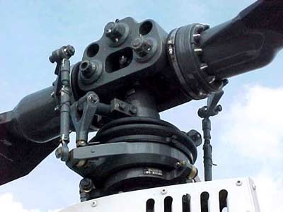
The
main rotor hub, where the rotor's drive shaft
and blades connect, has to be extremely strong
as well as highly adjustable. The swash plate
assembly is the component that provides the
adjustability.
Counter-Rotation Vs Contra-Rotation
One thing that
people often get confused with is the
difference between "Contra-Rotation" and
"Counter-Rotation". The terms are used
incorrectly more than you could possibly
imagine in books, manuals, and on web sites. I
wanted to take this opportunity to clear up
the difference between the two.
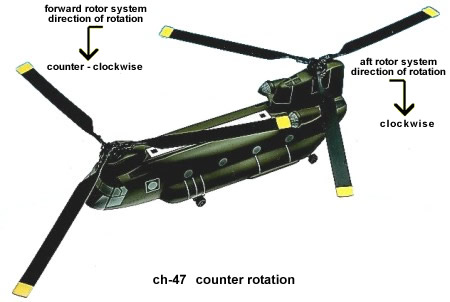
As you can see by
the first diagram, "Counter-Rotation" is where
there are two individual shafts driving two
propellers or rotors in different directions.
Although we have chosen to show this example
on a CH-47 Chinook from above, it is
exactly the same on a twin engine airplane
that has one propeller turning one way, and
one turning the opposite way (Like on a P-38
"Lightning"). Sometimes, as in the case of the
CH-47, the rotors will mesh, so the
synchronization of the systems is crucial.
On
airplanes, where the propellers do not mesh it
is not as critical that the systems are in
synch. In an airplane, if the systems are out
of synch, it can put undue stress on the
airframe, and cause harmonic vibrations
throughout the airframe. You can usually hear
an airplane that has the engines out of synch,
as it will make a varying strobe like sound.
Each propeller in
an airplane counter rotating system has its
own set of mechanical controls to vary the
pitch of the blades. Often it is a hydraulic
system, but in some cases (Like the P-38),
other means can be employed such as electric
power. In a helicopter, both rotors are
manipulated by one set of controls for the
pilot.
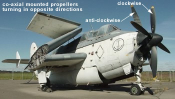
contra-rotation
"Contra-Rotation"
is where the propellers or rotors are mounted
"Co-Axially", meaning one in front of (or on
top of) the other on the same axis. Usually,
the drive mechanism is a single source, but
the direction of rotation is spilt by a
gearbox to drive the two systems in opposite
directions. This is usually done to reduce the
"P" factor or "torque" in a turn. While we
have chosen to show this example in the form
of a Royal Navy Fairey Gannet, it also
applies to helicopters (Like on the Soviet
"Hokum").
The main use for this on a
helicopter is that it negates the need for a tailrotor (Anti-torque rotor) to maintain
directional control at a hover. It also tends
to relieve some of the effects of retreating
blade stall as both sides of the aircraft have
advancing rotor blades.
In an airplane,
one set of controls will adjust the pitch of
both propellers at the same time. Usually, it
is done by varying hydraulic pressure in the
propeller hubs. In a helicopter, both rotors
are manipulated by a single set of pilot
controls as well, but two sets of control
tubes working off of two alternately rotating
swashplates are needed to adjust the rotors at
the individual hub.
The Forces At
Work
There are many
forces at work when a helicopter flies
including lift, drag, gravity, and thrust.
However there are specific
conditions experienced exclusively in rotary
wing flight.
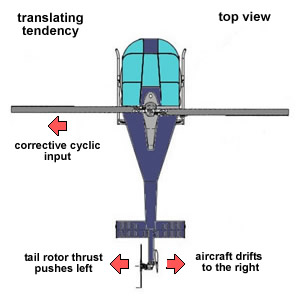
Translating
Tendency
Translating
tendency is defined by the textbooks as: The
tendency for a single rotor helicopter to
drift laterally, due to tail rotor thrust. One
may not think about how much thrust is
produced by the tail rotor, but we must
remember that the tail rotor has a 6 to 1
rotational ratio to the main rotor system.
It actually spins
6 times faster than the main rotor, so it can
compensate for the torque of the main rotor
without the need for a massive tail rotor
span. The thrust it produces tends to push the
aircraft sideways at a hover. We compensate
for this by adding left cyclic control inputs
(On American Helicopters, the opposite in
foreign manufactured aircraft, because their
rotor systems turn the opposite way from
ours). This makes the helicopter hang left
skid, or wheel, low at a hover. If you ever
see an American helicopter hovering, you may
notice this left side low condition. If you
ask a helicopter pilot how he is doing, and he
answers, " Left skid low", that means
everything is normal.
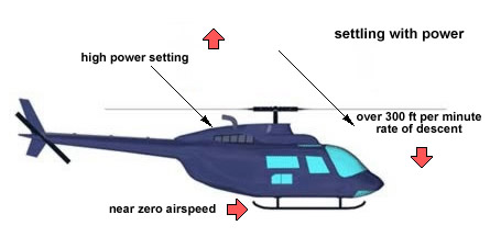
Settling With Power
Settling with power can be a dangerous
condition that any pilot may face, and if he
or she is not on their toes, it may cause a
serious uncontrollable situation. Settling
with power is basically when the helicopter
settles into the rotor wash produced by its
own main rotor system. It requires 3 key
elements to occur, and these conditions should
be avoided in combination with one another.
These are: A near
zero airspeed, up to 100% power applied, and a
better than 300 foot per minute rate of
descent. Once you have all of these situations
in occurrence, the aircraft will settle in its
own down wash from the rotor system. The only
way to recover is to gain forward airspeed and
allow the rotor system to fly into "Clean
air". Once the rotor system is clear of the
rotor-wash, it will become efficient again,
and the settling with power conditions will
cease to exist.
This can become a
real problem at an out of ground effect hover
(Above 10 feet from the ground), and during
landings.
'Settling With Power' or 'Settling in your own
downwash' is a dangerous situation that any
rotary wing machine can experience.
The term "Vortex Ring State" is used to
describe the actual swirling of the air within
the rotor system itself that causes "Settling
With Power".
Vortex Ring State can begin to occur when you
have 300 Feet per minute (FPM) as a rate of
descent.
Pilots
need to be aware of the situation and avoid it
at all costs.
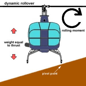
Dynamic
Rollover
Another
dangerous condition for a helicopter pilot to
experience is called dynamic rollover. It is
again, where you have a series of conditions
that combine to make a dangerous situation.
Once again, 3 key elements make up this
hazardous condition. They are: A pivot point,
a rolling moment, and weight equal to thrust
at some time during the manoeuvre. What
actually happens is that the helicopter, which
is still on the ground, will start to roll
over on its side using one skid, or wheel, as
the pivot point.
Once the aircraft
starts to roll, a downward collective movement
is the only thing that will stop the forces in
action from flipping the aircraft on its side.
By reducing the collective, the thrust to
weight ratio decreases, which allows the
aircraft to settle back down in a level
attitude. If this is done on sideward sloping
terrain, a collective reduction performed too
quickly can cause the aircraft to roll over on
the other side, down the slope. Care must be
exercised when performing slope operations,
but dynamic roll over can occur on the
flattest of surfaces if the pilot becomes
complacent.
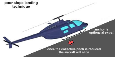
It is normal
practice to tackle a
slope from the side and not from the front or
back because most helicopters
have skid type landing gear with no brakes.
Skid gear will most likely slide down a hill
if the toes or heels of the skids are pointed
up hill once the power is taken away holding
the aircraft in place.
Once that force
is no longer applied, the weight of the
aircraft will get it started sliding and,
depending on the slope, could pick up so much
speed that it crashes severely at the bottom
of the hill. The ones that have wheels
and brakes could slide also depending on the
degree of slope and condition of the ground.
Other reasons not
to attack a slope from the front or back is
that the tail boom may strike the hill before
the skids do (Again, depending on the degree
of the slope) or the rotor system may impact
the hill before the skids do. Usually, if the
standard 8 degrees of slope are used as a
maximum, then a sideward approach to the slope
will have the skids touching before the rotor
system. Care should be used when passengers
depart the aircraft on a slope as they may
walk into the rotor if they go up hill. Always
brief the passengers to leave the aircraft on
the down slope side of the aircraft.
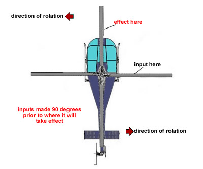
A rotating body acts like a gyroscope and the
forces that act upon the gyroscope require
some adjustment to allow for the rotation
itself. A spinning body will take inputs
placed at one part of the cycle of rotation
and react later in the cycle of rotation. Now
without getting too technical, the main thing
to remember here is that with the rotation
comes some extra planning. If you want a
control input to take effect, you just have to
be a little ahead of where you want it to
happen. In this case, 90 degrees before the
spot where the action you desire is to take
effect is where you have to plan to put it
into the system. Input is placed in one
location and as the blade swings 90 degrees
more in the direction of rotation, the desired
effect will be realized.
|