A nozzle is a
relatively simple device, just a specially shaped tube through
which hot gases flow. However, the mathematics which describe
the operation of the nozzle takes some careful thought. As
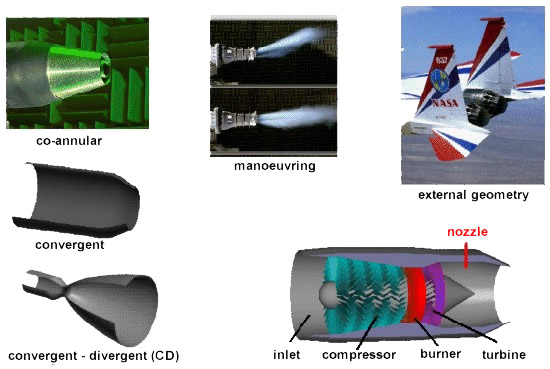
shown above, nozzles come in a variety of shapes and sizes
depending on the mission of the aircraft. Simple turbojets,
and turboprops, often have a fixed geometry convergent nozzle
as shown on the left of the figure. Turbofan engines will
sometimes employ a co-annular nozzle as shown at the top left.
The core flow will exit the centre nozzle while the fan flow
exits the annular nozzle. Afterburning turbojets and turbofans
often have a variable geometry convergent-divergent (CD)
nozzle as shown on the left. In this nozzle, the flow first
converges down to the minimum area, or throat, then is
expanded through the divergent section to the exit at the
right. The variable geometry causes these nozzles to be heavy,
but provides efficient engine operation over a wider airflow
range than a simple fixed nozzle. Rocket engines usually have
a fixed geometry CD nozzle with a much larger divergent
section than is required for a gas turbine.
All of the
nozzles we have discussed thus far are round tubes. Recently,
however, engineers have been experimenting with nozzles with
rectangular exits. This allows the exhaust flow to be easily
deflected, as shown in the middle of the figure. Changing the
direction of the thrust with the nozzle makes the aircraft
much more manoeuvrable.
Because the
nozzle conducts the hot exhaust back to the free stream, there
can be serious interactions between the engine exhaust flow
and the airflow around the aircraft. On fighter aircraft, in
particular, large drag penalties can occur near the nozzle
exits. A typical nozzle-afterbody configuration is
shown in the upper right for an F-15 with experimental
manoeuvring nozzles. As with the inlet design, the external
nozzle configuration is often designed by the airframer. The
internal nozzle is usually the responsibility of the engine
manufacturer.