|

aircraft engine
history
a
brief
overview of aircraft engine development
By Kimble D. McCutcheon
During the period between the World Wars, aircraft engines
improved dramatically and made possible unprecedented progress
in aircraft design. Engine development in those days, and to a
large extent even today, is a very laborious, detailed process
of building an engine, running it to destruction, analysing
what broke, designing a fix, and repeating the process. No
product ever comes to market without some engineer(s) having
spent many long, lonely, anxious hours perfecting that
product. This is especially true of aircraft engines, which by
their very nature push all the limits of ingenuity, materials,
and manufacturing processes.
aircraft engine
requirements and measures of performance
In order to compare engines, we must
discuss the special requirements of aircraft engines and
introduce some measures of performance. The requirements are
in some ways contradictory, and therein lies the engineering
challenge. For the purpose of this discussion, we will compare
the Curtiss OX-5 to the Wright R-3350. The OX-5, though hardly
state-of-the-art at the end of WWI, was the first U.S.
aircraft engine to be mass-produced and was produced in such
quantities that war surplus ones powered aircraft for the next
twenty years. The Wright R-3350, completely state-of-the-art
at the end of WWII, had been developed for the Boeing B-29
(the aircraft that dropped the atomic bomb on Japan) and was
widely used in airline service through the middle sixties.
RELIABILITY The first and most important requirement for an
aircraft engine is that it must be reliable. At the end of
WWI, the Curtis OX-5 regularly failed after only 30 hours of
operation. During the 1950’s, airlines often ran Wright
R-3350s 3000 hours. This hundred-fold increase in reliability
is one of the fascinating subjects of this discussion. These
values are usually expressed in Time Between Overhaul (TBO),
but are not really directly comparable. Pilots often ran OX-5s
to failure and forced landings were common. Airlines, on the
other hand, figured a forced landing might scare their
passengers, so they put on multiple engines, kept good records
about how long particular engines could be expected to last,
and presumably overhauled them before they failed. The point,
however, is that engines got much, much better during the
period of our interest.
power
to weight ratio
Secondly, aircraft engines must produce as
much power as possible while weighing as little as possible.
This is usually expressed in terms of pounds per horsepower
(lb/hp). One way to make an engine more powerful is to make it
bigger, but this also makes it heavier. Moreover, if you shave
away metal to make it lighter, parts start to crack, break,
and generally become less reliable. You can see the
conflicting objectives faced by the engineer. Another option
is to get more power from a given size. Engine size is usually
expressed in cubic inches (cu in) of swept volume (the volume
displaced by all the pistons going up and down). If you
can make an engine get more horsepower per cubic inch (hp/in),
then you have made it lighter. The OX-5 displaced 503 cu/in,
weighed about 390 pounds and produced 90 HP (0.18 hp/in, 4.33
lb/hp). By contrast, the R- 3350 displaced 3350 cu in, weighed
3670 lb., and produced as much as 3700 hp (1.10 hp/in, 0.99
lb/hp), improvements of six-fold in horsepower per cubic inch
and over four-fold in power-to-weight ratio. FUEL CONSUMPTION
Finally, an aircraft engine must be fuel-efficient. A great
deal of the take-off weight of an airplane is dedicated to
fuel. So if one can make the engine(s) more fuel efficient,
less fuel must be carried to go the same distance, and more
bombs, passengers or freight can be carried instead. Fuel
usage is expressed in terms called Brake Specific Fuel
Consumption (BSFC). This is the number of pounds of fuel an
engine uses per horsepower per operating hour (lb/hp/hr). Fuel
is measured in pounds because a pound of fuel is always the
same amount of fuel, while a gallon of fuel at 100 degrees
weighs less than a gallon of fuel at 20 degrees. BSFC for the
OX-5 was about .53 lb/hp/hr, while the R-3350 was about .38
lb/hp/hr. If one could compare a ten hour flight under similar
conditions and power settings, one would have to carry 371
pounds of fuel for the OX-5 verses 257 pounds of fuel for the
R-3350, or a savings of 114 pounds. This may not seem like
much of a difference, but again, it is an unrealistic
comparison because of the huge difference in the output of the
two engines. In reality, tens of thousands of pounds of fuel
were carried in the huge transports of the 1950’s, and
improvements in fuel consumption made significant differences
in overall aircraft capability. Indeed, ocean-crossing
airliners such as the Lockheed Super Constellation and Douglas
DC-7 would have not been economically feasible without the
superb fuel consumption of advanced engines.
Areas of
Improvement
So how were these remarkable improvements
made? They were done by systematically improving seven areas
of engine design and construction: Arrangement, materials,
cooling, induction, lubrication, fuels, and operation. Most of
these are necessarily interrelated, as we shall see. In
addition to engine improvements, there were also important
advances in aircraft and propeller design. Perhaps the
greatest engine-related airframe advance was the development
of the NACA cowl that reduced the cooling drag of air-cooled
radial engines to levels that were competitive with
liquid-cooled engines. The greatest propeller advance was the
introduction in the 1930s of controllable pitch and later
automatically controlled constant speed. Constant-speed
propellers allow engines to produce maximum take-off power by
turning maximum RPM due to fine blade pitch, and then cruise
at efficient lower RPM through the selection of a coarse blade
pitch. We will now briefly discuss each of these areas of
improvement. Many of the engines have companion articles that
go into greater technical detail.
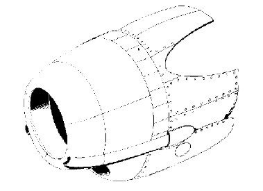
Figure 1. The NACA low-drag cowl
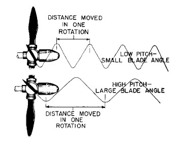
Figure 2. The variable pitch propeller
Arrangement
Engine arrangement refers to the
organization of multiple cylinders around the crankshaft.
There are really only two ways of doing this - to put them all
in a row along the length of the crankshaft, as in the inline
engine, or to put them around a single throw of the crankshaft
like spokes in a wheel, as in radial engines. For a long time,
aircraft designers were overly concerned with frontal area of
engines, because this had to be accounted for in the design of
the airframe, and produced drag. In-line, opposed, and V-type
engines provide the least frontal area because cylinders are
"stacked" one behind the other. Unfortunately, any engine
flexes as it runs and must be stiff enough so that it does not
crack its components. This requires a very heavy crankcase and
crankshaft. The radial configuration avoids this problem by
having a short, stiff crankcase and crankshaft.
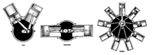
Figure 3. Engine arrangements
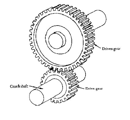
spur and pinion
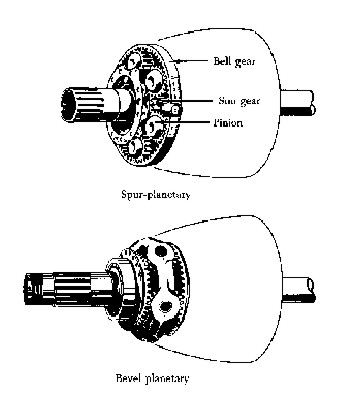
Figure 4. Propeller reduction gearing
Over time, designers learned to stack
multiple rows of radial cylinders together, and since this had
the best power-to-weight ratio, it became the preferred
configuration for high-power engines. Advances in cowl design
all but eliminated any frontal area advantage of the in-line
and V-type engine. Many other configurations were tried, but
none ever equalled the multi-row radial engine for
power-to-weight ratio. The Curtiss OX-5, Rolls-Royce Merlin
(V-1610), and Ranger V- 70 are examples of V-type engines.
There are many examples of multi-row radial engines, with the
Wright R-3350 and Pratt & Whitney R-4360 being the latest and
most highly refined. There are also many examples of opposed
engines.
While engines are able to achieve higher
power by turning higher RPM, propeller RPM is limited by tip
speed. In order to remain efficient, propeller tips must
remain below the speed of sound. Otherwise, engine power is
wasted overcoming the excess drag of propeller tips making
shock waves and noise. The logical answer to this paradox lies
in the use reduction gearing, allowing the engine to turn
faster than the propeller. Propeller reduction gearing was a
feature of the 1903 Wright "Flyer", but it took a considerable
amount of work to sort out the details of reduction gearing
for high-powered radial engines, particularly multi-row
radials. Each power stroke of the engine tends to slightly
wind up the crankshaft. The propeller resists this winding, or
torsion. When the power stroke subsides, the somewhat springy
crankshaft unwinds producing a phenomenon called torsional
vibration. This plagued early engines, was not very well
understood, and was generally fixed by resorting to huge spur
or helical-cut gears with massive teeth that could resist the
shock loads imposed on the reduction gearing by torsional
vibration. Later engines saw the development of planetary
reduction gears with very close tolerances that mitigated some
of the effects of torsional vibration. It all came to a head
when controllable-pitch propellers fitted to early Wright
R-1820 Cyclones began breaking propeller shafts. It turned out
that the greater weight of controllable-pitch propellers
increased the effective mass of the propeller and allowed
vibrations of certain frequencies to actually fatigue the
propeller shaft until it broke. The solution was to fit tuned
dynamic torsional vibration absorbers in the form of massive
dynamic counterweights loosely attached to the crankshaft so
they were free to move slightly in the plane of rotation.
Weight and pendulum length were calculated so that the dynamic
counterweight vibrated at the same frequency as the power
strokes of the engine, but out of phase so as to cancel out
the effect of the torsional vibration. Both the Wright R-3350
and Pratt & Whitney R-2800 encountered another
vibration-related problem. These were the first multi-row
radials with nine cylinders per row, and they too began
breaking engine parts early in development. The problem in
this case was traced to a different mechanism, but was still
vibration related. Radial engines with the master
/articulating rod system produce slightly different motions
for each piston/rod combination, and can never have perfect
balance. This becomes more of a problem as the number of
cylinders per row increases. The unbalance tends to make the
engine move in a circle in the same plane as the cylinders.
Because two-row radials have a two throw crankshaft, two such
motions acting at twice crankshaft speed tend to cause the
engine to wobble about its centre main bearing. This wobble
causes the propeller change its plane of rotation, and
eventually fatigues the propeller shaft to the breaking point.
The solution is rotate correctly sized counterbalances at
twice crankshaft speed and in same direction as crankshaft
rotation.
|
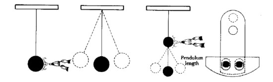
If a
simple pendulum is given a series of regular impulses at
a speed corresponding to its natural frequency (using a
bellows to simulate a power impulse in an engine) it
will commence swinging, or vibrating back and forth from
the impulses. Another pendulum, suspended from the
first, would absorb the impulses and swing itself,
leaving the first stationary. The dynamic damper is a
short pendulum hung on the crankshaft and tuned to the
frequency of the power impulses to absorb vibration in
the same manner |
Figure 5.
Principle of tuned dynamic torsional vibration absorber
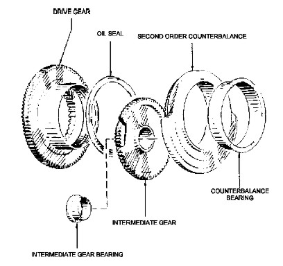
Figure 6. Second order counterbalance
Materials
An engine designer, always striving for low
weight, typically makes everything out of the lightest
material that is practical. This usually translates into the
use of aluminium for the bulky components (such as pistons,
cylinder heads, and crankcases) and steel for the highly
stressed components (such as crankshafts, connecting rods, and
gears). Over time, designers created lighter and stronger
alloys, developed ways to harden materials so they lasted
longer, and most importantly, learned ways of forming metal
components so that the "grain" of the metal (metals have grain
just like wood) was correctly aligned to handle the stresses
imposed on the part. This process, called forging, vastly
improved the strength of almost all engine components.
Consider the strength of a crankshaft carved from a single
plank of wood. Though the grain of the wood is in line with
the bearing journals of the crankshaft, the throws of the
crankshaft would be cut across the grain and would be quite
weak. This was the precise problem of early engines.
Crankshafts were machined from giant chunks of steel that had
been hot-rolled so that all the grain of the metal was in one
direction. The forging process takes a hot chunk of metal and
hammers it into roughly the final shape. The metal grain is
forced to conform to the final shape and is much stronger.
Nearly all engines made after 1920 used forged crankshafts,
connecting rods, and pistons. As forging processes became
better understood and huge hammer forges became available,
larger engine parts such as crankcases were forged. The Pratt
& Whitney R-1340 "Wasp" was the first American radial to use a
forged crankcase.
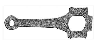
Figure 7. Etched connecting rod rough forging
showing metal flow lines
Further benefits were obtained by improving
the art of casting large chunks of aluminium. In the early
days, crankcases with integral cylinders could not be cast
because no one knew how to make such large castings without
flaws. In-line and V-type engines with the cylinders separate
from the crankcase could never be as stiff as a single large
casting, and consequently, were heavier than necessary. The
Curtiss OX-5 is an example of a separate-cylinder engine while
the Rolls- Royce Merlin is an example of a one-piece block.
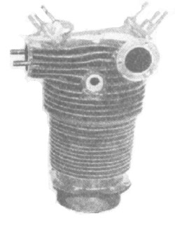
Figure 8. Wright J-5 cylinder
Cylinder heads
are another example of the progress of the casting art.
Compare the Wright J-5 "Whirlwind" with the Pratt & Whitney
R-2800. Each engine has cast cylinder heads, but the fins on
the J-5 are much further apart and much less deep than those
of the R-2800. Considerable experimentation was required to
perfect these extremely complex castings, and much work was
required to produce the pattern and the mould for each one.
The result was an enormous increase in fin area and better
cooling. Later heads were forged, with their fins cut by
special automated machines. Not only were the forged heads
about twice as strong as the best cast ones, but the fins
could be deeper and closer together, resulting in higher
powers and better cooling. Forged heads can be seen on the
Wright R-3350.
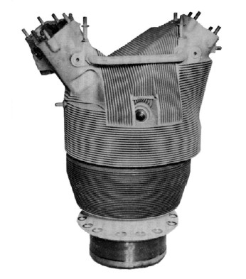
Figure 9. R-2800 cylinder
As Pratt & Whitney began to extract more
and more power from their early engines, they began to have
occasional master rod bearing failures in the lead/copper plain
bearings originally used. A massive amount of effort was
thrown into experiments with different bearing materials.
Eventually, it was discovered that a silver bearing plated
with lead and then indium had extremely good wear properties.
In the 1950’s, an airline returned one of these bearings to
Pratt & Whitney for rework after it had run over 7,000 hours.
Pratt & Whitney returned it saying there was no wear,
approving it for continued service. Finally, improvements in
the materials and fabrication techniques for valves made
significant improvements in the power and durability of
engines. Most of this work was done first at the Royal
Aircraft Factory at Farnborough, England and later at McCook
Field in Dayton, Ohio. Experimentation with simple single
cylinder engines determined the best materials and geometry
for valves, guides and seats. The sodium-cooled exhaust valve
was also invented at McCook field. This valve featured a
hollow stem partially filled with liquid sodium. As the valve
opened and closed, the sodium sloshed about, moving heat away
from the head to the stem of the valve. All Wright and Pratt &
Whitney radial engines use this style of exhaust valve.
Cooling
No debate was more heated in engine design
circles than the one over cooling. As with most heated
debates, neither side in retrospect knew what it was talking
about. The choices were liquid cooling, where, as in
automobile engines, the cylinders are surrounded by a liquid
coolant (usually water and anti-freeze) which removes excess
heat from fuel combustion and is circulated to a radiator
where it gives up this heat to the air. Air-cooled engines,
like lawn mowers, have cooling fins on the cylinders, and give
up their heat directly to the air. The subject is complex, and
it took many years to sort it out completely (indeed, it may
still not be sorted out). In the early days, air-cooling was
so poorly understood that almost no one could make it work at
all, and certainly not for any high-power applications. Liquid
cooling at least allowed the production of four or five
hundred horsepower engines. But these were unreliable engines.
The Army, who in those days had the luxury of flight over
land, preferred liquid cooled engines because of their lower
frontal area. The Navy, on the other hand, discovered that
fully twenty-five percent of engine failures were due to
failure of the cooling system, and declared that "Liquidcooled
airplanes make about as much sense as aircooled submarines!"
During the twenties, air cooling became much better
understood, and high-power air-cooled engines flourished to
such an extent that all work on liquid cooled engines ceased,
and both the Navy and Army had to pay premiums to attract any
interest among engine companies an liquid-cooled engines. The
major improvements were made at McCook Field, and appear on
all air-cooled engines since. Innovations included an
aluminium cylinder head with the valves set at a very wide
angle to allow plenty of airflow around the exhaust port. A
steel cylinder liner with machined cooling fins was screwed
and shrunk into this aluminium head, resulting in a gas-tight
seal between the head and barrel. The exhaust valve was the
sodium-cooled variety discussed above. Nearly all aircooled
engines have cylinders of this design (it first appeared on
the Wright J-5 "Whirlwind").
Induction
Induction is the process by which fuel is
mixed with air and introduced into the cylinder. Engine power
is a function of the pressure at which induction occurs. By
forcing more of the fuel-air mixture into the engine at higher
pressure, impressive additional power can be achieved. This
process is called supercharging. Superchargers are pumps that
increase the pressure of the fuel-air charge. In aircraft
engines, these nearly always take the form of centrifugal
compressors.
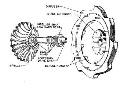
Figure 11. Supercharger impeller and diffuser
Improvements in superchargers greatly
assisted the increased production of power, and also allowed
the engine to produce sea-level power at considerably greater
altitudes than non-supercharged engines. Early superchargers
were just "rotary induction systems", and served little
purpose other than to assure equal distribution of fuel to all
cylinders. As engine development progressed, superchargers
became better and better compressors by providing higher
pressure while consuming less power.
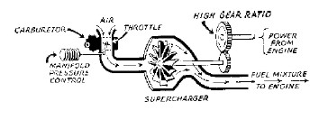
Figure 12. Single-stage supercharger
Supercharger design is a tricky business.
Not only must the supercharger be efficient to avoid wasting
engine power and excessively heating the intake charge, but it
must also have a pressure rise and pumping volume that is
carefully matched to the engine it is a part of. The first
American production engine to use a supercharger was the Pratt
& Whitney R-1340 "Wasp". All early engines used superchargers
from the same source - General Electric. By the 1930’s, it
became clear to both Wright and Pratt & Whitney that the GE
superchargers were very inefficient, and both companies
established their own in-house supercharger design teams.
These designs went on to set records for efficiency and
pressure ratio. As supercharger boost levels improved, the
need arose to tailor supercharger output to the engine power
and altitude. This was the reason for development of two-speed
and two-stage superchargers. The Pratt & Whitney R-2800 in the
F4U Corsair is an example of the two-stage supercharger. The
huge casting behind the last row of cylinders is almost
entirely a two-stage supercharger. Output air from the first
stage is ducted to the second stage for further compression.
An intercooler, which is a sort of air radiator to cool the
compressed intake charge was often fitted to these
highly-boosted engines.
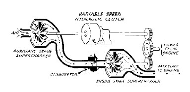
Figure 13. Two-stage supercharger
The huge induction system on big engines
with high boost pressures full of explosive fuel/air mix can
be blown apart by backfires resulting from improper operator
technique. This is one of the difficulties with having the
carburettor at the entrance to the induction system. A more
acceptable solution is fuel injection, preferably directly
into the cylinder. In this situation, the induction system is
just pumping air, so designers do not have to worry about
backfires, uneven mixture distribution, and carburettor ice.
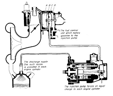
Figure 14. Direct fuel injection
Another type of supercharging that is very
effective is turbo supercharging. In this application, engine
exhaust velocity is used to drive a turbine which is connected
to a centrifugal compressor which rams more air into the
engine. The combined package is called a turbocharger. A valve
called the waste gate controls turbine speed. The turbocharger
has an advantage of not robbing as much horsepower from the
engine as gear-driven superchargers do.
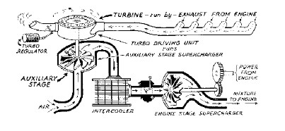
Figure 15. Turbo-supercharger with intercooler
General Electric built all of the
turbochargers used in World War II. All high-altitude bombers
(B-17, B-24, B- 29) and many fighters (P-38, P-47) used
turbochargers to maintain full engine power up to an altitude
of eighteen to twenty thousand feet.
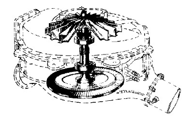
Figure 16. General Electric turbosupercharger
Near the end of World War II, someone got
the idea to harness the wasted energy in engine exhaust by
using the exhaust to drive a turbine that was coupled to the
engine crankshaft. This process is called turbo-compounding.
Although numerous engines had experimental test programs with
turbo-compounding, only the Wright R-3350 Turbo Cyclone ever
saw wide service. Referring to Figure 18, notice the three
large pressure recovery turbines spaced equally around the aft
side of the engine. Each of these was fed by the exhaust from
six cylinders and contributed nearly 200 additional horsepower
(600 total) to the engine output. Another advantage of
turbo-compounding is the exceptionally good fuel consumption.
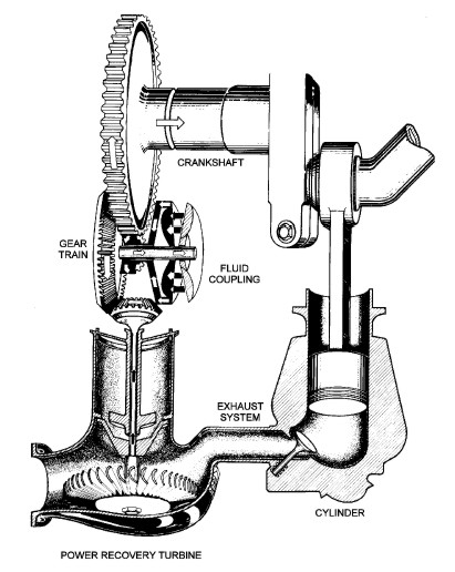
Figure 17. Turbo-compounding schematic
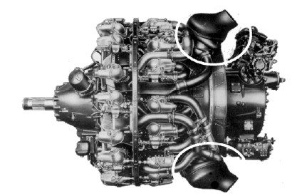
Figure 18. Wright Turbo-Compound 18 showing two of three
power recovery turbines
Lubrication
Early engines were lubricated with
vegetable oils usually castor oil. Castor oil was chosen
because it had nearly constant viscosity (resistance to flow)
across its temperature range, and because it coated the metal
surface well so that the lubricating film was not easily
scraped or washed away. It had the unfortunate characteristic
of turning to a gel after being heated and then cooled. For
this reason, it was and still is used only in "total loss"
lubrication systems such as rotary engines, model airplane
engines, and outboards. The introduction of high-quality
mineral oils allowed recirculation of the oil (drastically
reducing oil consumption) as well as the production of greater
power by assuring that metal parts were separated by a thin
film of oil and never came in contact with one another. To do
this, the oil has to be able to resist mechanical pressure,
heat, the tendency to oxidize, and the tendency to lose
viscosity. Originally, only straight mineral oils were used.
In the 1950’s, additive packages were introduced to make the
oil "Ashless-Dispersant" (AD). AD oils leave no residue when
they burn away (hence the ashless) and are formulated to keep
contaminants in suspension until the oil is changed. Nearly
all oil in use today is the AD type. Eventually, synthetic
oils with superior lubrication, viscosity, and stability will
probably replace mineral oils.
Fuels
Of at least equal importance to all other
areas of actual engine development is the development of
fuels. During WWI, pilots noticed that gasoline refined from
Romanian crude oil, ran better than that refined from
California crude. After the war, an investigation of this
phenomenon revealed that "bad" gasoline caused the engine to
detonate. Detonation is a condition in which the fuel-air
mixture in the cylinder burns explosively rather than
smoothly. It was further discovered that pure iso-octane, a
gasoline constituent of a certain molecular structure, was
about the best that could be had. Hence, the Octane rating
system was born. Early gasoline was between 25 and 50 octane.
Combinations of poor cooling, high compression ratios (the
ratio of cylinder volume at the top and bottom of the piston
stroke), and/or excessive supercharging lead to detonation,
often with disastrous results. In the late twenties it was
learned that the addition of tetraethyl lead to gasoline
drastically improved its octane rating, so much in fact that
it was better than isooctane. Fuels that test better than iso-octane
are rated with Performance Numbers (PN) These improved fuels,
often as high as 145 PN, allowed higher compression ratios and
higher supercharger pressures which resulted in doubling or
trebling of engine power. It is interesting to note that the
Allison and Rolls-Royce engines used in WWII Allied fighters
got about the same horsepower from around 1700 cubic inches
that German engines got from 2600 cubic inches. This was
almost entirely due to use of 115/145 PN aviation gasoline in
Allied aviation engines verses the 80-90 octane German fuels.
Toward the middle of World War II, another
technology came on the scene that further improved engine
takeoff horsepower ratings. This was Anti-Detonation
Injection, or ADI. ADI was simply a pump that during extreme
power conditions such as take-off, injected a mixture of water
and alcohol into the induction system. The alcohol was
primarily to prevent freezing of the water. ADI greatly
improved detonation margin, but since it consumed large
quantities of water (which is heavy), it was typically only
used during take-off or for short times in combat.
Operation
The final area of improvement is that of
actual operation of the engine. When the R-3350 entered
service in World War II, it often did not run more than 100
hours before having to be overhauled. In airline service, it
would sometimes last over 3,000 hours. It is true that the
early R-3350s had design problems that were fixed as the
engine matured, but another important factor was how the
engine was operated. The early engines were run very hard and
very hot, often overheated, flown by inexperienced crews, and
maintained by poorly trained mechanics. In airline service,
engines were treated very well, kept cool, flown and
maintained by experienced and competent crew. They were also
better instrumented and better data was kept which allowed
correlation between operational practice and longevity. One of
the most useful instruments introduced during the war was the
torquemeter. This device measured the amount of power actually
being delivered to the propeller and allowed the crew to
select power settings accurately and to lean the engine
correctly to prevent overheating.
Conclusion
By 1950, aircraft piston engines had
reached their pinnacle of development. They had become light,
powerful, reliable, and fuel-efficient. But they had also
reached their pinnacle of complexity and probably power. It is
doubtful that anything larger than the R- 4360 could have ever
been cost-effective simply because of the number of precision
parts and amount of maintenance required. Even the R-4360 was
never popular in commercial service because it typically
required many hours of maintenance for each flight hour, and
sophisticated fault diagnosis equipment to boot. Cylinders
larger than around 200 cubic inches or producing more than
about 200 horsepower were not practical, and engines with more
than about 28 cylinders were not practical. It follows that
engines larger than six or seven thousand horsepower were also
not practical. Around 1945, engineering effort at the major
engine plants began to turn away from piston engines to
engines with much greater potential for development - jets.
|
