According to Arthur Nutt, Chief Engineer of the
Curtiss Aeroplane and Motor Co., Inc., it was in
April, 1926, that a systematic study was first
started on the design of a 600 horsepower
air-cooled aircraft engine. The first steps in
this study were to analyse the types of engines in
use at that time and then to study the
possibilities of the different forms of engines
which would be suitable in the large size
contemplated. The types that were finally selected
for study were as follows: Nine Cylinder Single
Row Radial, Fourteen Cylinder Two Row Radial,
Sixteen Cylinder X, Twelve Cylinder Vee, Twelve
Cylinder Hexagon. In making this study ten
important characteristics were borne in mind. 1.
Low weight per horsepower. 2. Head resistance and
propeller efficiency. 3. Visibility from the
pilot's cockpit. 4. High crankshaft speed. 5.
Overhead valve gear for high speed. 6. Exhaust
arrangement. 7. Control of cooling air. 8.
Application of reduction gears. 9. Overall
dimensions particularly diameter and length. 10.
Smoothness of operation.
Nine Cylinder Single Row Radial.-This
type would require an engine of from 1,800 to
1,900 cubic inches to develop about 600
brake-horsepower at a speed in the neighbourhood
of 1,900 r.p.m., which is probably a rather
optimistic speed at which to expect to run an
engine of this power and displacement, owing to
the fact that the size of the cylinder bore is
reaching a point where cooling is difficult, and
the reciprocating weights on one crankpin (even
though it may be of the split crankshaft and solid
big end type) would be a difficult problem. The
outside diameter of a nine cylinder radial engine
of this power would be 56 inches to 60 inches in
diameter which presents a very large frontal area
with severe blanketing of the propeller, resulting
in poor propeller efficiency. The added diameter
increases the resistance so much that it has been
found by experience that the larger radial engines
in Pursuit planes make practically no more speed
than the lower horsepower radial engines with the
smaller diameters. Of course, the rate of climb is
increased but this does not offset the
disadvantage of carrying high powered engines
using more fuel without gaining more top speed.
The exhaust problem on a nine cylinder radial
becomes more difficult as the size of the engine
increases. The manifold must be made very large in
order to decrease the back pressure. The
manifolding assembly then becomes very heavy,
unreliable and cumbersome, resulting in the
necessity of locating it between the propeller and
cylinders where it undoubtedly has a detrimental
effect on the cylinder cooling as well as making
the cylinders very inaccessible. A large diameter
radial engine does not lend itself to good cowling
and the adaptation of shutters for control of
cylinder temperatures and oil temperatures under
various weather conditions. It is necessary to use
push rod valve mechanism with the attendant
difficulty of lubrication of the rocker arms, and
the ball and socket joints. The lubrication cannot
be fully automatic without adding a great many
pipe fittings and tubing which would not be
reliable, would increase the expense and would be
very unsatisfactory.
Fourteen-Cylinder Two Row Radial.-This
type of engine has been used by several
manufacturers in powers up to 450 horsepower, and
is objectionable on account of the lack of
satisfactory cooling of the
rear row of cylinders, since the cylinder spacing
is so close when the outside diameter of the
engine is held to a minimum that the rear
cylinders get hot air from the front cylinders.
The push rod valve mechanism is also
unsatisfactory on account of the necessity of
staggering the cylinders to a great degree in
order to keep the engine diameter down, resulting
in high angularity on the push rods and
possibilities of increased wear on these parts.
The weight per horsepower on the double row radial
is slightly higher than the single row radial but
it has the advantage of a small diameter which was
the reason for investigating this type of engine.
The displacement would have to be approximately
1,800 cubic inches, which would allow smaller
cylinders than could be obtained in a nine
cylinder type. Both these engines, the nine
cylinder radial and fourteen cylinder using push
rod valve gears, are probably limited in engine
speed although this engine speed has in the past
few years been increased slightly over what was
originally thought could be used with this type of
valve gear. There is no question, however, that
the push rod valve gear is inferior to the
overhead type when high engine speeds are used.
Sixteen-Cylinder X.-The
X sixteen-cylinder engine has not been given a
great deal of consideration on account of the
large number of cylinders making the engine more
expensive and the necessity of using very heavy
counterbalances on the crankshaft to make the
engine run smooth. The engine would also be
heavier than the radial types on account of the
longer crankshaft, although the diameter would be
very satisfactory.
Twelve-Cylinder Vee.-This
type of engine has been built successfully with
air cooling, it has one very great objection,
namely, its overall length which automatically
gives a high weight per horsepower as compared
with the other types of air-cooled engines. This
overall length is necessary on account of the
large cylinder centres necessary to get cooling on
each cylinder barrel and on the cylinder head. The
air-cooled Vee engine is eight or ten inches
longer than a water-cooled engine of the same
bore, however, the engine has a-very great
advantage of being able to run at high engine
speeds on account of the overhead valve gear and
the light reciprocating parts on the crankshaft.
The exhaust arrangement is very satisfactory,
particularly when the engine is built in the
inverted form. The cooling air to the cylinders
can be controlled by means of shutters, if
necessary, and the air to the crankcase can also
be controlled by shutters. One of the biggest
problems with this engine, however, is proper
intake manifolding.
Considering all of these types of engines the
rotary inductor and supercharger have been
included in the study of the design, therefore,
when connecting the supercharger in the Vee engine
to the cylinders, the straight or gallery type
manifolds have usually been employed which are
extremely unsatisfactory at high altitude, owing
to the fact that the gas distribution with this
type of manifold is very poor. The engine runs
very well at sea level where the manifolds are not
subjected to the cold air blast and where the heat
of the mixture is higher owing to the higher
initial temperature of the charge. In order to
apply a satisfactory manifold to this engine
weight and frontal area are increased, inasmuch as
the manifold arrangement must be on the outside of
the cylinder banks.
Twelve-Cylinder Hexagon Type.-After
making the above study it was decided to attempt a
combination of the radial and Vee engine which
would satisfactorily combine the good features and
do away with the objectionable features of both.
The type of engine selected is that for which the
Curtiss company has coined the name "Hexagon." In
other words, the Vee engine was cut into three
sections, these sections of four cylinder Vee
engines being placed in radial form 120 degrees
apart, resulting in a two row radial
twelve-cylinder engine, one row directly behind
the other. By blanking off the rear end of the
exhaust Vee in each of the three Vees, Vee engine
cooling was obtained.
The feature of the low weight per horsepower of
the radial was partially maintained, as there is
no question that the single row radial is the
lightest form of engine at a given r.p.m. and
displacement that is known today. However, by
increasing the engine crankshaft speed this
difference was offset. Second, the head resistance
was kept very low, the engine outside diameter
being 45 inches, and the cowling diameter 39
inches, which results in high propeller efficiency
as the ratio of the diameter of the propeller to
the diameter of the engine becomes larger than on
the big radial engines, leaving the propeller tips
in clear unobstructed air in a symmetrical form
around the engine. In fact, the propeller has less
flutter when operating in front of a symmetrical
body than it would behind a form of engine such as
the inverted Vee, particularly if the propeller
runs very close to the engine. On account of the
small diameter and a short engine very high
visibility was obtained. With six cylinders in a
radial row there are large spaces, 60 degrees
between each cylinder bank, which permits
visibility as obtained on a 39-inch diameter since
the 45-inch diameter prevails only at the overhead
valve gear covers which extend for only a very
short part of the circumference and are
streamlined easily.
With only six cylinders on a crankpin the weight
of reciprocating parts was greatly reduced
permitting higher crankshaft speeds. Overhead
valve gear similar in design to the D12 valve gear
was used which again permitted the higher
crankshaft speeds. The exhaust arrangement is
exactly the same as on any Vee engine with the
addition of an extra row of exhaust ports at the
bottom of the engine which can be manifolded with
a muffler in a single row at the two sides and.
bottom adding practically no head resistance and
not interfering with visibility. The cooling air
to the cylinders can be controlled as on the Vee
engine. Reduction gears of either the concentric
type or the spur type can be used, the latter
possibility being a very great advantage on the
engine and one which cannot be used on any other
form of engine without interfering with cylinder
cooling or increasing the frontal area of the
engine, as would be the case on the inverted Vee
engine should the reduction gear or the spur type
be raised above the crankshaft centre line. The
application of the spur gears in this way on the
inverted Vee engine would also entirely ruin the
visibility from the pilot's cockpit. The spur
reduction gears would not interfere with cowling
or visibility on the Hexagon engine and they would
raise the centre of the propeller shaft, giving
more clearance for the propeller which naturally
would be larger in diameter if run at a slower
speed. The overall length of the Hexagon type of
engine is only about eight inches more than the
single row type which is a negligible figure when
the installation in an airplane is considered.
There is also no question that the larger the
number of cylinders on an engine of this power the
smoother the operation of the engine will be.
Twelve cylinder torque has been demonstrated
repeatedly to be very much more satisfactory than
the torque from a smaller number of cylinders of
the same size when the engine is run at the same
crankshaft speed.
It
is not possible to completely balance the
nine-cylinder radial engine or any other single
row engine using the articulated type of rods.
These engines do not run as smooth as the twelve
cylinder, but they have been found to be
satisfactory in service. The balance of the
articulated rods on the Hexagon type is perfect,
inasmuch as one row of the cylinders completely
balances out the other row of cylinders on the
opposite crank throw and it was only necessary to
put enough balance weights on the crankshaft to
take care of the unbalanced couple existing.
The above outline describes roughly the
arrangement of the engine, however, a few details
making this combination possible are given below:
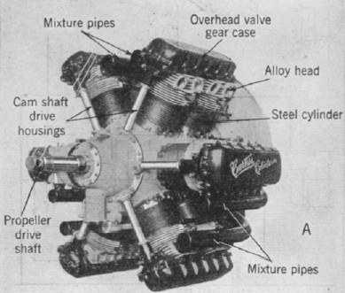
The cylinder construction is of the conventional
type with the exception that a four valve flat
head cylinder is used similar to the water-cooled
Conqueror engine. Bronze seats are inserted in the
aluminium cylinder head and the steel cylinder-is
screwed in the aluminium head in the usual manner.
Each cylinder in a bank has a large pilot on the
top end which fits into a casting bridging the two
cylinders. This casting is held in place with
studs and nuts and carries the double camshaft
bearings. The two camshafts on each bank of two
cylinders are driven by spur gears at the
propeller end, one of these spur gears being
mounted on an idler shaft below the two camshafts.
The' idler shaft is driven through bevels and a
master gear on the front end of the crankshaft,
all of the vertical shafts being driven from this
master gear. Each pair of camshafts has a serrated
face coupling for timing, adjustment.
The crankshaft, which is a two throw, 180 degree
crank, is mounted on two Norma-Hoffman roller
bearings one at each end. The centre main steel
backed babbitt lined bearing is mounted on a large
split circular bearing support which is large
enough to. clear both crankpins enabling the shaft
to be dropped into the crankcase which is of the
barrel type. The crankcase is split at right
angles to the crankshaft between the two rows of
six cylinders being bolted together on inverted
flanges on the inside of the crankcase before the
cylinders are put in place. This gives a very
clean exterior on the crankcase and the internal
flange forms a support for the centre main
bearings. The nose piece on this engine which is
clearly shown at Figs. 665 and 666 contains only
the cluster of bevel gears for driving the
camshaft, and the oil pressure strainer. The
strainer is located at this end of the engine for
the purpose of accessibility and permits the use
of an oil seal for forcing oil into the crankshaft
for lubrication purposes. A large deep groove ball
bearing for both radial and thrust purposes is
used at the forward end of the nose of the engine
on the crankshaft.
The connecting rods are of the split type, very
carefully keyed together with integral keys. Owing
to the fact that the number of cylinders are even,
the rods are perfectly symmetrical permitting the
bolts to be placed' very close to the babbitt
lined bearing shells, thus eliminating the big
objection which is always present in a radial
engine with an odd number of cylinders in a row.
The connecting rod in the single row radial engine
must be unsymmetrical making it very hard to get a
satisfactory bolting arrangement on the split
connecting rod. Pistons are of the hollow head
type and are of the conventional ribbed design
which have been used by Curtiss for many years.
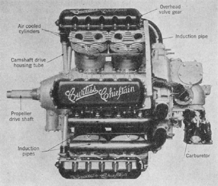
The engine is fitted with a rotary inductor or
supercharger which will give sea level power at
12,000 feet. It is of the General Electric
Company's centrifugal type and is mounted in the
rear of the engine as shown at Fig. 666 C, being
driven by four spur gears, two being on a
jackshaft. One main shaft is carried through the
diffuser of the supercharger to drive all
accessories which are mounted on the back of the
engine. A very unusual and novel method of
mounting accessories has been employed on this
engine. All accessories are mounted in such a
position that they are accessible when an engine
is installed in an airplane.
The starter and magneto are mounted on opposite
ends of a horizontal cross shaft driven from very
large bevel gears from the shaft which was carried
through the diffuser. This same shaft through the
diffuser carries a larger helical gear which
drives two vertical shafts in the rear gearcase.
Two distributors are driven from helical gears
from each of these two shafts, the oil pump being
driven off the lower end of one of these shafts
and the gasoline pump off the lower end of the
other shaft. The generator is mounted in a
vertical position, on the top of the gearcase
driving through bevel gears. In other words, there
are only three bevel gears on the rear end of the
engine, driving accessories. In addition the oil
pump is driven from the lower end of one of these
shafts and the fuel pump from the lower end of the
other. The generator is mounted in a vertical
position on top of the gearcase, and is driven
through bevel gears. There are thus three bevel
gears at the rear end of the engine for driving
accessories. The two gun control drives are taken
from the top ends of the vertical shafts, while
the tachometer drives are taken from the rear ends
of the camshafts, as desired.
A
carburetor intake elbow is cast integral with the
rear gearcase and a single Stromberg carburettor
with economizer is fitted. Lubrication is by the
regular Curtiss system, to which have been added a
number of special features that will be described.
Oil from the pressure pump is led through a steel
tube to the pressure oil strainer on the nose of
the engine; it passes through this strainer into
the crankshaft and thence to the two connecting
rod bearings and the centre main bearing, which is
a plain bearing. To the bearings of all the
articulated rods the oil is index-fed, and the
spray from these bearings lubricates the cylinder
walls and the piston pin bearings. Oil under
pressure is index-fed to all of the plain bearings
in the gearcase of the engine and also to the ball
and roller bearings wherever this was found
necessary. Oil is conducted to the camshaft
bearings through the vertical drive shafts and is
returned to the main crankcase by geartype oil
pumps formed by casings built around the spur
gears which drive the camshafts. Making these
gears do the additional duty of oil pumps called
for very little weight increase. Two main
scavenging oil pumps are provided, one taking oil
from the front and the other from the rear end of
the engine, both returning the oil to an outside
tank.
One of the most interesting features of the engine
is the manner in which the cooling problem has
been solved. In the past it has been considered a
very difficult task to assure equal cooling of
air-cooled cylinders where one or more of a bank
are masked by the forward cylinder thereof. In the
Chieftain every other space between cylinder banks
is baffled at the rear by a plate to which the
cowl is fitted snugly. The air current induced by
the motion of the plane, upon striking this
baffle, is deflected sideways against the rear
cylinders and compelled to pass through the space
between the two cylinders of a bank and around the
back side of the rear cylinder, from the exhaust
compartment to the inlet compartment. From the
inlet compartment it passes into a space in the
fuselage back of the engine, whence it escapes
through louvres in the cowling at the forward part
of the Curtiss Falcon plane.
Another interesting problem connected with the
design of this engine was that of the firing
order. A single row radial engine requires an
unequal number of cylinders if explosions are to
be equally spaced. In analysing the problem as
relating to the hexagon type, it was found
possible to jump from the front to the back row
and to the front again. Explosions evidently must
be spaced 60 degrees of crank motion, which is the
angular distance between cylinder banks. Thus,
after one forward cylinder has been fired, the
cylinder next forward in the direction of rotation
(clockwise) may be fired, or, alternately, the
rear cylinder of the bank directly opposite this
one. Thus there are at least three possible firing
orders. Of these the one in which front and rear
cylinders always succeed one another was chosen.
The tests conducted on this engine during the past
eight months have indicated that the engine is a
very satisfactory type. It develops 615 brake
horsepower at 2,200 r.p.m. The weight, including
exhaust flanges, exhaust heater, including the
heater on the induction passage elbow and the
throttle barrels of the carburettor (this weight
is not usually included in the weight of
air-cooled engines as built today) is 900 pounds,
which gives a specific weight of 1.46 pounds per
horsepower which compares very favourably with any
air-cooled engine built today. The frontal area
per horsepower of this type of engine is
approximately one-half of the nine-cylinder engine
of the same horsepower. This engine has the same
frontal area with less head resistance on account
of its better aspect ratio than the conventional
200 horsepower radial engine and with this
decreased head resistance it has the advantage of
over three times the horsepower. The engine has
been developed primarily for pursuit and
observation types of airplanes but with future
development and the adaptation of reduction gears
it promises to be a satisfactory engine for slower
types of planes.
CHARACTERISTICS-CURTISS CHIEFTAIN R1600 ENGINE
Hp. (rated) at 2200 r.p.m .....................600
Model
...................................................H-1640
Type of engine
.....................................Static Air
Cooled Hexagon
No. of cylinders
....................................12
Arrangement of cylinders: 2
radial rows of 6, front
cylinders
directly in line
with rear
cylinders
Dia. of engine
.......................................45 in.
Dia. of cowling
......................................39 in.
Bore
......................................................5
5/8 in.
Stroke
...................................................5
1/2 in.
Displacement
......................................1640 cu. in.
B.Hp .
..................................................615
Ignition system
....................................Splitdorf
Magneto
Carburetor
...........................................Stromberg
NA-U8j
Cruise fuel consumption at 2000 r.p.m 53 lb. per
b.hp. per hr.
Oil consumption
...................................020 lb. per
b.hp. hr.
Speed of propeller
................................Crankshaft
Rotation of propeller
.............................Clockwise
Weight of engine
..................................900 lb.